


Extender Series • Quick Start Guide
QS-1
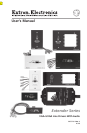
Quick Start Guide — Extender Series
SmMan_main_template_V4_051605
W
Installation and service must be performed by authorized
personnel only. These products must be used with UL
approved, grounded electrical boxes.
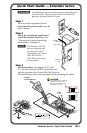
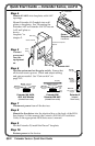
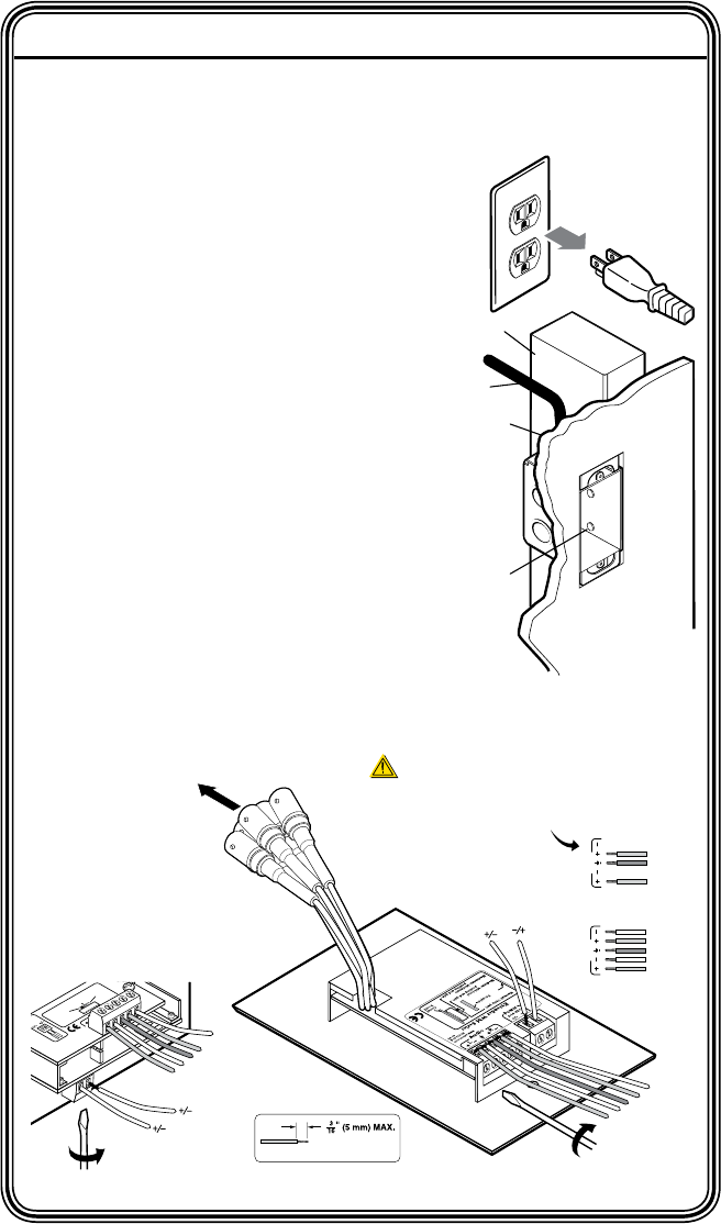
Step 1
Turn all of the equipment off and
disconnect the power cords from the
power source.
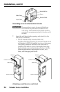
Step 2
Select the installation location and
install the electrical wall box. See
“Preparing the site and installing
the wall box” in chapter 2.
N
The Extender AAP EX
does not require a wall
box because it will be
installed into an Extron
HSA 400 Series or
HSA 800 Series surface
access product.
Step 3
Attach the cables. See pages 2‑6, 2-7, and
2‑9. For the Extender AAP EX, install the unit
into the faceplate of an Extron HSA 400 Series or
HSA 800 Series surface access product before attaching the cables.
To RGB
Video Equipment
Extender Series
9
-1
8
VD
C
wer
Gain
(S
w
itch
is on
th
e
lo
w
er circu
it b
oa
rd
.)
Maximum
Max. peaking
& gain
Medium
– Mid-lev
el
peaking & gain
Normal
Unity
gain
www.extron.com
33-612-02
Rev. C
02 05
L
Audio
R
Sleeve (s)
Left Tip
Left Ring
9-18 VDC
Power
Sleeve (s)
Left Tip
Right Tip
Left Ring
Right Ring
9-18 VDC
Power
Audio
Unbalanced Output
Left Tip
NO Ground Here
Sleeve(s)
Right Tip
NO Ground Here
Balanced Output
Sleeve(s)
Left Tip
Right Tip
Left Ring
Right Ring
L
Audio
R
L
Audio
R
Do not tin the wires!
CAUTION
For unbalanced audio, connect the
sleeve(s) to the ground contact.
DO NOT connect the sleeve(s) to
the negative (-) contacts.
Installation
Cable
Cable Clamp
Wall Stud
Screws or
Nails
Quick Start Guide