


Extender Series • Installation
Installation, cont’d
2-10
PRELIMINARY
a
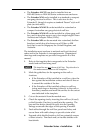
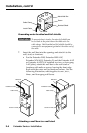
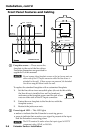
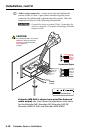
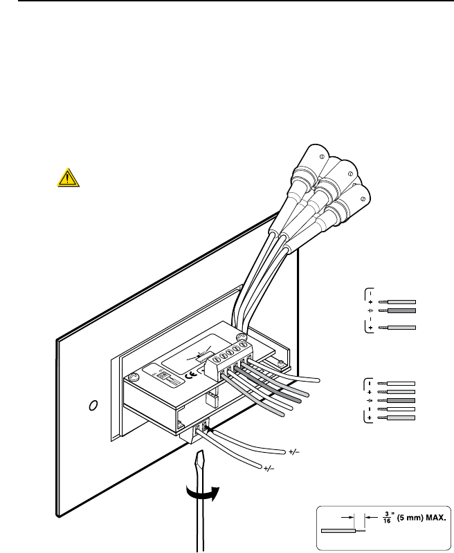
Audio output connector — Insert wires into and tighten the
screws on this 3.5 mm, 5-pole direct insertion captive screw
connector for unbalanced or balanced audio output. Wire the
connector as shown in the following illustrations.
C
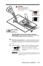
Connect the sleeve to ground (Gnd). Connecting the
sleeve to a negative (-) terminal will damage the audio
output circuits.
Extender Ser
ies
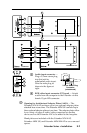
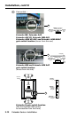
9-18 VDC
Power
Gain
(Switch is on t
he lower circuit
board.)
Maxim
um
Max. peakin
g
& gain
Medium
– Mid-le
vel
peaking &
gain
Normal
Unity
gain
w
w
w
.extron.com
33-612-02
R
ev
. C
02 05
L
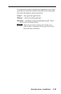
Audio
R
Audio
Unbalanced Output
Left Tip
NO Ground Here
Sleeve (s)
Right Tip
NO Ground Here
Balanced Output
Sleeve (s)
Left Tip
Right Tip
Left Ring
Right Ring
Sleeve (s)
Left Tip
Right Tip
Left Ring
Right Ring
L
Audio
R
L
Audio
R
9-18 VDC
Power
CAUTION
For unbalanced audio, connect the
sleeve(s) to the ground contact.
DO NOT connect the sleeve(s)
to the negative (-)
contacts.
Do not tin the wires!
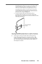
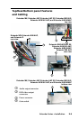
Extender WM AUS is shown here wired for balanced
audio output; the circuit board configuration is the same
for the Extender MK, Extender AAP, Extender AAP EX,
Extender AKM UK AAP, and Extender AKM MAAP