


Installation, cont’d
IN1404XT Video Scaler and Switcher • Installation2-4
Cr
R
RGBHV
RGBS
RGsB,
Component
Y
G/Gs
Cb
BH/S V
S-video
Composite
video
Cr
R
Y
G/Gs
Cb
B H/S V
(Pr)
R
Y
G/Gs
(Pb)
Cr Y Cb
(R-y) Y (B-Y)
B H/S V
Cr
(C)
R
Y
G/Gs
Cb
B H/S V
Cr
R
Y
(Vid)
G/Gs
Cb
B H/S V
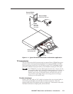
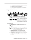
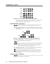
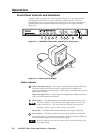
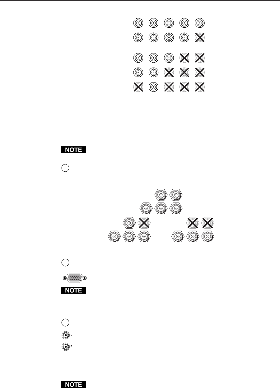
Figure 2-3 — Connections for various input video formats
The audio bass, treble, and balance levels for each input can be individually
set via the front panel or the RS-232 link. See chapter 3, Operation, and
chapter 4, Programmer’s Guide for details.
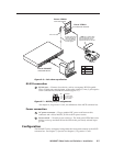
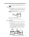
Standard output connections
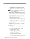
The two standard outputs, consisting of five BNC connectors and a 15HD
connector, output the identical video signal and the same sync format.
5
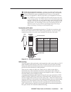
Output BNC connectors— Connect an RGBHV, RGBS, or RGsB video display
to these female BNC connectors. Figure 2-4 shows how to connect the various
video formats.
V
RGBHV
H/S
R
G/Gs
B
V
RGBS
H/S
R
G/Gs
B
V
RGsB
H/S
R
G/Gs
B
Figure 2-4 — BNC output connections for RGBHV and RGBS video
6
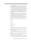
Output 15HD connector — Connect an RGBHV, RGBS, or RGsB video
display to this female 15HD connector.
The two standard output connectors, BNCs and 15-pin HD, are individually
buffered (even when input 4 is configured as passive (unscaled). They can
both be simultaneously connected and transmitted up to 100 feet on high
quality coax cable without degradation of either output.
7
Output audio connectors— Connect an audio device, such as an amplifier or
powered speakers, to these left and right RCA connectors.
By default, the audio output follows the video switch. Audio breakaway,
commanded via the RS-232 link, allows you to select from any one of the
audio input sources. See chapter 3, Operation and chapter 4, Programmer’s
Guide for details.
TP video output connection
RJ-45 termination must comply with the TIA/EIA T 568A or TIA/EIA T 568B
wiring standards for all connections.