


2-5IN1404XT Video Scaler and Switcher • Installation
8
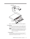
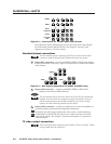
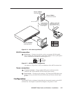
RGB video transmission connector — Connect one end of a TP cable to this
RJ-45 female connector. Connect the other end of the TP cable to an optional
Extron VTR001CM or other compatible Extron TP receiver. See Optional
Accessories, in Appendix A, Reference Information, for compatible TP receivers.
The VTR001CM can receive RGBHV and RGSB signals from the scaler with
no loss of image quality. The VTR001 CM can also receive RGsB signals from
the scaler. However, the red, green, and blue video signals’ black levels are not
clamped to a 0V reference, as for RGBHV or RGBS. For most displays, this is
not a problem. On some displays (such as some LCD displays) however, the
black levels of the red, green, and blue signals may change as the average
picture level changes, resulting in an unacceptable image.
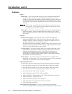
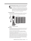
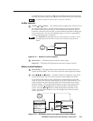
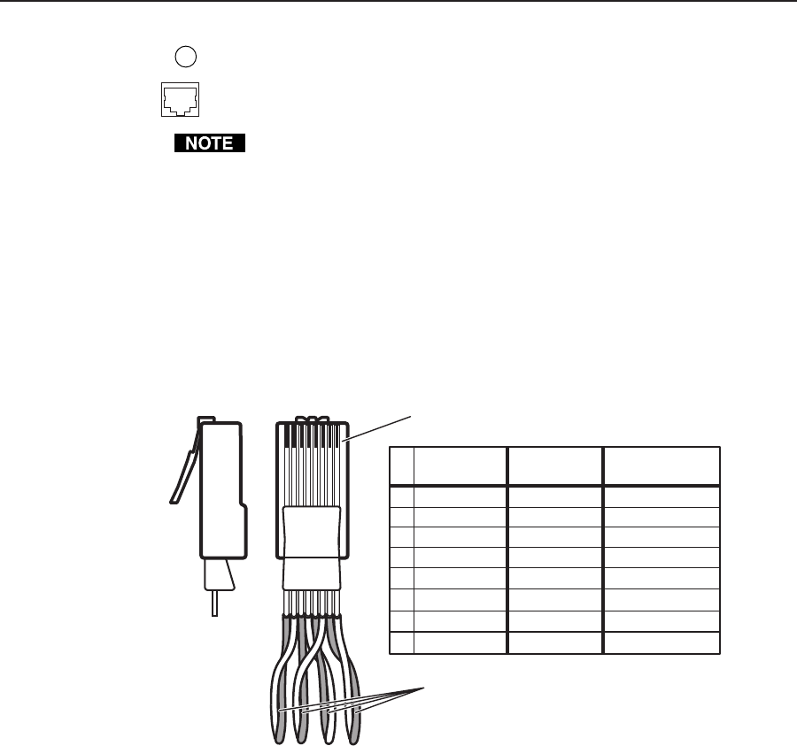
Termination of TP cable
Figure 2-5 details the recommended termination of TP cables in accordance with
the TIA/EIA T 568A and TIA/EIA T 568 B wiring standards. You can use either
standard, but ensure you use the same standard on both ends of the cable.
Clip DownSide
1
1&2
3&6 4&5
7&8
2345678
12345678
Pin
Wire color
RGB video signal
1
White-green
Red/V. sync+
2 Green
Red/V. sync-
3
White-orange
Power
4
Blue Green+
5
White-blue
Green-
6
Orange
Power
7 White-brown Blue/H. sync+
8
Brown
Blue/H. sync-
RJ-45 connector
Twisted Pairs
Wire color
TIA/EIA T-568-A
TIA/EIA T-568-B
White-orange
Orange
White-green
Blue
White-blue
Green
White-brown
Brown
Figure 2-5 — TP cable termination
Cable testing
To ensure proper cable termination, each transmission cable system that uses CAT 5
cable should be tested (Extron’s skew-free UTP cable does not need to be tested).
Testing the cable from the RJ-45 connections at the transmitter and receiver gives
the most accurate indications of cable problems.
There are two varieties of cable runs: simple runs, in which a single cable is
terminated only at the transmitter and receiver, and complex runs, which can
include patch bays and multiple terminations and lengths of cable. In either case,
the entire cabling system should be tested.
A complete test measures cable length and tests the wire map, attenuation, NEXT,
PSNEXT, ELFEXT, PSELFEXT, return loss, ACR and PSACR. All of these tests are
critical for digital data transfer, but not for analog video. While all of these tests are
important indicators of the quality of the cable termination, the most critical testing
parameters for video transfer are wire map (T-568-A or B termination) and pair
length measurements. The largest concern is equalization of skew between cable
pairs. Cable systems of 300 feet or less should exhibit no transmission problems if
they pass at least CAT 5 channel certification testing.