


Installation, cont’d
CrossPoint 450 Plus and MAV Plus Switchers • Installation
2-6
PRELIMINARY
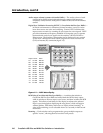
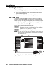
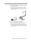
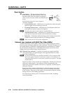
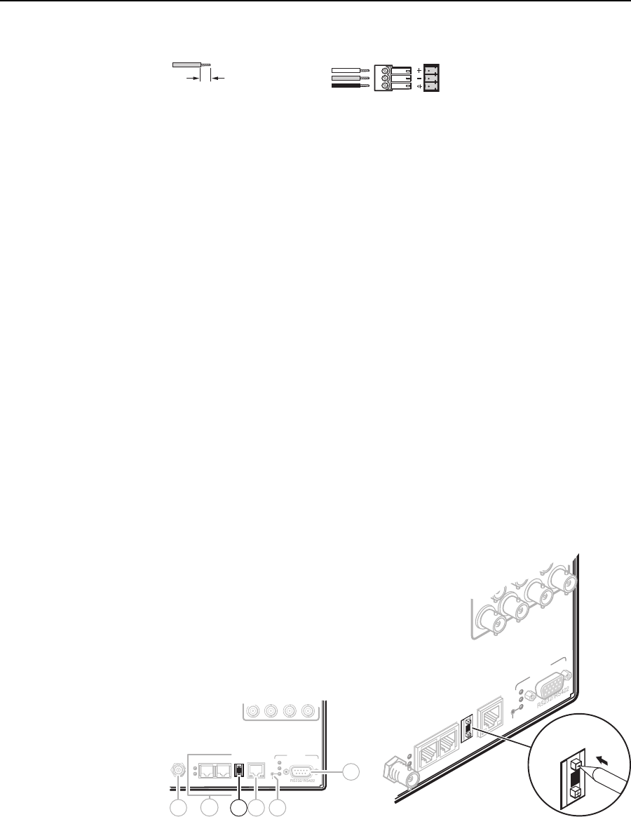
See fi gure 2-7 to properly wire an output connector for the mono audio BME.
Tip
Ring
Sleeves
0.2” (5 mm) max.
Do not tin the wires!
Figure 2-7 — Captive screw connector wiring for mono audio output
N
The length of exposed wires is critical. The ideal length is 0.2” (5 mm).
• If the stripped section of wire is longer than 0.2”, the exposed wires may
touch, causing a short circuit between them.
• If the stripped section of wire is shorter than 0.2”, wires can be easily pulled
out even if tightly fastened by the captive screws.
The volume level for each output can be individually set via the front panel
or Ether net or RS-232/RS-422 control. See chapter 3, Operation, chapter 4,
SIS Programming and Control, chapter 5, Matrix Software, and chapter 6,
HTML Operation for details.
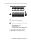
BME connection and selection
N
BME 0 should house the front panel controller and be the BME used for system
control and monitoring via the serial ports and Ethernet LAN link.
f
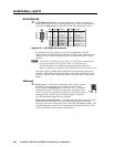
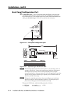
BME address switch — Each BME must be set to a unique address of 0
through 5.
Addresses 6 through 9 are invalid.
The addresses used in the system must be sequential with no skipped
numbers.
Sync BMEs cannot be set to address 0.
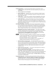
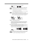
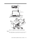
To set the BME address, press the + and - buttons on the BME Address switch
on the rear panel of the switcher (fi gure 2-8).
64636261
LAN
ACT
LINK
RESET
REMOTE
Rx
Tx
Rx
Tx
BME COMM
IN OUT
EXT
SYNC
Rx
Tx
4
-
+
BME
ADDRESS
6
8
9 1011
7
Tx
Rx
BME COMM
OUT
REMOTE
Rx
Tx
LAN
ACT
LINK
EXT
SYNC
BME
ADDRESS
4
4
64636261
Figure 2-8 — Setting a BME address (video BME shown)