


Operation, cont’d
CrossPoint 450 Plus and MAV Plus Switchers • Operation
3-42
PRELIMINARY
Selecting the rear panel Remote port protocol and baud rate
The switcher can support either the RS-232 or the RS-422 serial communication
protocol, and operate at 9600, 19200, 38400, and 115200 baud rates. The settings of
these variables can be viewed and changed from the front panel.
View and confi gure the switcher’s serial communications settings as follows:
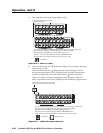
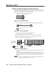
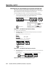
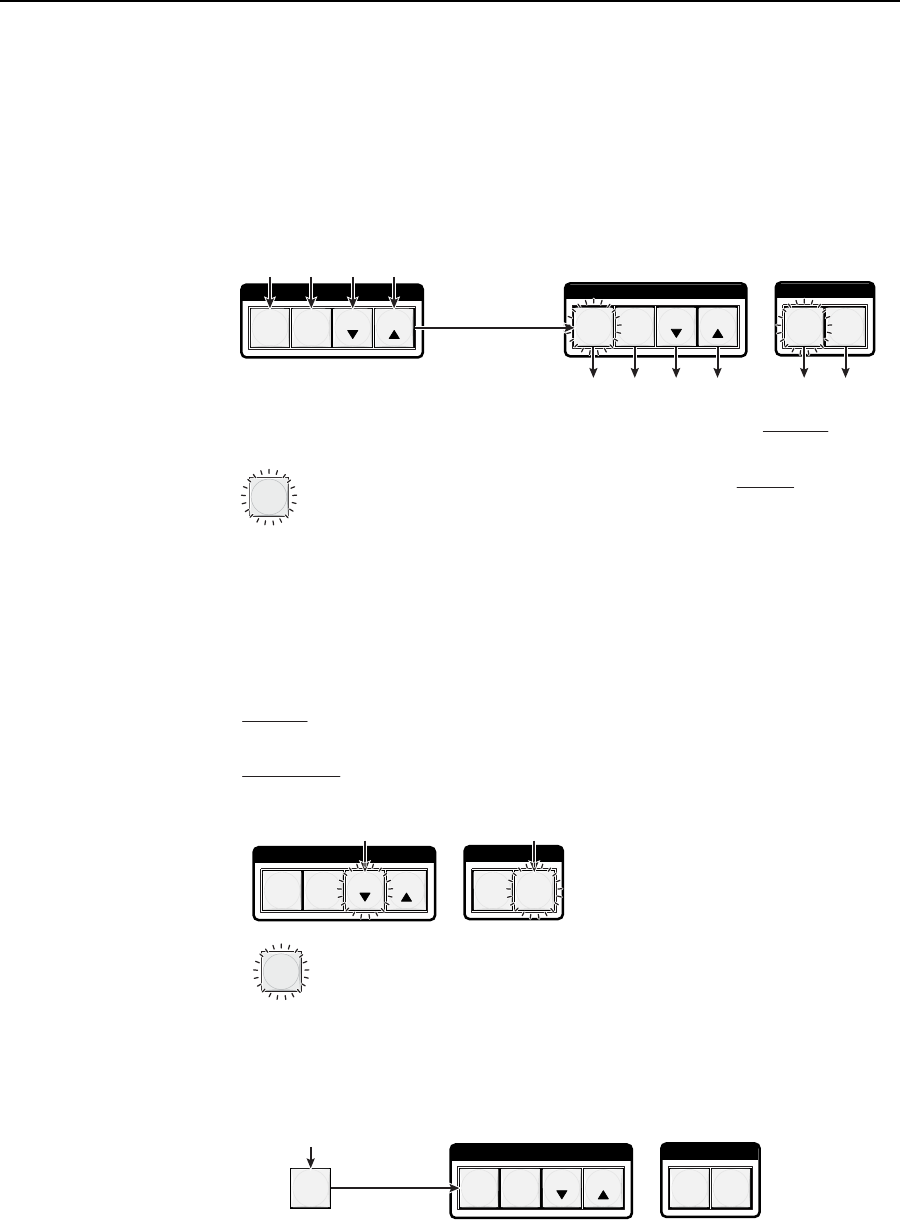
1. To enter Serial Port Confi guration mode, simultaneously press and hold all
Control buttons (Enter, Preset, View, and Esc) (fi gure 3-67).
C O N T R O L
PRESET
ENTER
I / O
RGBHV AUDIO
C O N T R O L
PRESET
ENTER
ESCVIEW
ESCVIEW
2 seconds
All Control buttons light with one flashing.
Both I/O buttons light with one flashing.
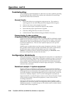
The flashing Control button indicates the baud rate as follows:
Enter — 9600 Preset — 19200
View — 38400 Esc — 115200
The flashing I/O button indicates the protocol as follows:
RGBHV/Video — RS-232 Audio — RS-422/RS-485
In this example, the port is set to RS-232 at 9600 baud.
Press and hold the Enter, Preset, View, and Esc buttons.
= Blinking button
Figure 3-67 — RS-232/RS-422 and baud rate display
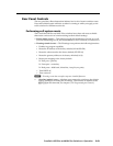
2. Release the Control buttons.
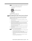
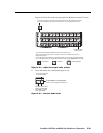
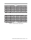
3. To change a value, press and release the button that relates to the desired
value (fi gure 3-68).
C O N T R O L
PRESET
ENTER
I / O
RGBHV AUDIO
ESCVIEW
Press and release the button(s) to configure the port as
follows:
Baud rate:
Enter — 9600 Preset — 19200
View — 38400 Esc — 115200
Serial protocol:
RGBHV/Video — RS-232 Audio — RS-422/RS-485
The selected buttons blink and the others remain lit.
In this example, the port is set to RS-422 at 38400 baud.
= Blinking button
Figure 3-68 — RS-232/RS-422 and baud rate selection
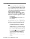
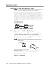
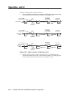
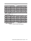
4. Press and release an input or output button to exit the Serial Port Confi guration
mode (fi gure 3-69).
C O N T R O L
PRESET
ENTER
I / O
RGBHV AUDIO
ESCVIEW
5
All Control and I/O buttons return to unlit or background illumination.
Press and release an
input or output button.
Figure 3-69 — Exit Serial Port Confi guration mode