


Installation, cont’d
CrossPoint 450 Plus and MAV Plus Switchers • Installation
2-8
PRELIMINARY
RS-232/RS-422
h
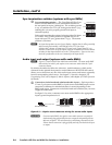
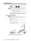
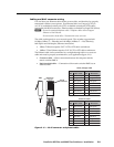
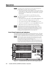
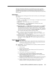
RS-232/RS-422 connector — Connect a host device, such as a computer,
touch panel control, or RS-232 capable PDA to the switcher via this 9-pin D
connector on BME 0 only for serial RS-232/RS-422 control (fi gure 2-10).
RS-232FunctionPin Function
1
2
3
4
5
6
7
8
9
—
TX
RX
—
Gnd
—
—
—
—
Not used
Transmit data
Receive data
Not used
Signal ground
Not used
Not used
Not used
Not used
—
TX–
RX–
—
Gnd
—
RX+
TX+
—
Not used
Transmit data (–)
Receive data (–)
Not used
Signal ground
Not used
Receive data (+)
Transmit data (+)
Not used
RS-422
5
1
9
6
RS232/RS422
REMOTE
Figure 2-10 — RS-232/RS-422 connector
See chapter 4, SIS Programming and Control, for defi nitions of the SIS
commands (serial commands to control the switcher via this connector) and
chapter 5, Matrix Software for details on how to install and use the control
software.
N
The switcher can support either the RS-232 or RS-422 serial communication
protocol, and operate at 9600, 19200, 38400, or 115200 baud rates.
See Selecting the rear panel Remote port protocol and baud rate in
chapter 3, Operation, to confi gure the RS-232/RS-422 port from the front panel.
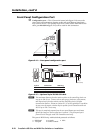
If desired, connect an MKP 2000 or MKP 3000 remote control panel to the
switcher’s RS-232/RS-422 connector. Refer to the MKP 2000 Remote Control
Panel User’s Manual or the MKP 3000 Remote Control Panel User’s Manual for
details.
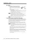
Ethernet
i
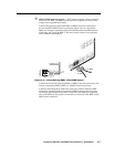
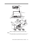
Ethernet port — If desired, for IP control of the system, connect
the matrix switcher to a PC or to an Ethernet LAN, via this
RJ-45 connector on BME 0 only. You can use a PC to control the
networked switcher with SIS commands from anywhere in the
world. You can also control the switcher from a PC that is either
running Extron’s windows-based control program or that has
downloaded HTML pages from the switcher.
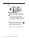
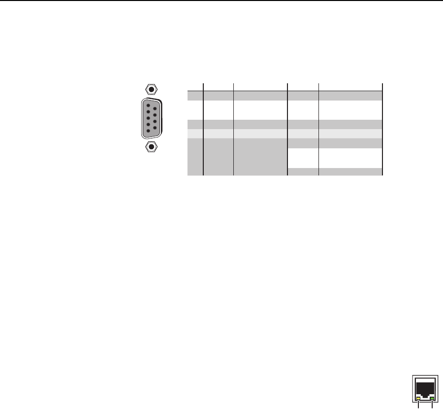
Ethernet connection indicators — The Link and Act LEDs indicate the status
of the Ethernet connection. The Link LED indicates that the switcher is
properly connected to an Ethernet LAN. This LED should light steadily. The
Act LED indicates transmission of data packets on the RJ-45 connector. This
LED should fl icker as the switcher communicates.
Link
LED
Activity
LED