


2-7
CrossPoint 450 Plus and MAV Plus Switchers • Installation
PRELIMINARY
g
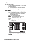
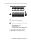
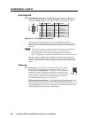
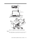
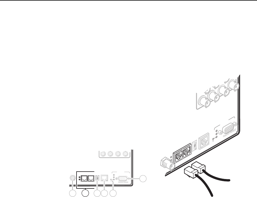
BME COMM interconnect ports — If the matrix switcher system consists of
more than one BME, the BMEs must be connected together in a daisy chain
using Extron-supplied RJ-45 cables.
Connect the fi rst daisy chain from BME 0’s BME Comm Out connector to
the nearest BME’s BME Comm In connector (fi gure 2-9). In a rack where
BMEs are arranged so that their physical location matches the BME address
numbering, this would be BME 1. But since not all systems are confi gured
alike, call this module BME n.
64636261
LAN
ACT
LINK
RESET
REMOTE
Rx
Tx
Rx
Tx
4
-
+
BME COMM
IN OUT
BME
ADDRESS
EXT
SYNC
Rx
Tx
8
9 10611
7
RESET
REMOTE
Rx
Tx
LAN
ACT
LIN
K
64 63 62 61
BME COMM
OUT
BME
ADDRESS
EXT
SYNC
4
To BME
From BME
Figure 2-9 — Daisy-chaining BMEs (video BME shown)
Connect the next RJ-45 cable from BME n’s BME Comm Out connector to the
nearest unconnected BME’s (BME n+1’s) BME Comm In connector.
Continue connecting RJ-45 cables from each daisy-chained module’s BME
Comm Out connector to the next module’s BME Comm In connector until
all modules are included in the chain. When all of the BMEs are connected,
each of the BMEs in the system is connected to at least one other BME via the
BME Comm connectors.