


VersaTools
®
MTP Series • Installation
VersaTools
®
MTP Series • Installation
Installation, cont’d
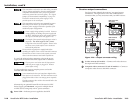
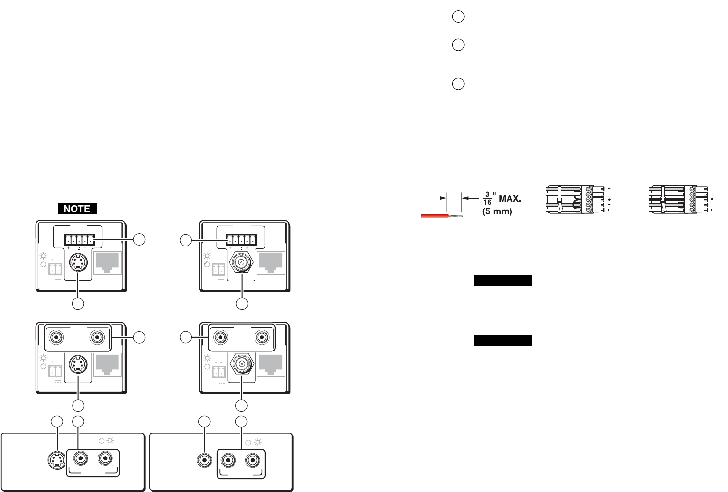
1
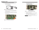
S-video connector (SV models) —
Connect an S-video input to
this 4-pin mini DIN connector.
2
Composite video connector
(CV and AV models)
— Connect a
composite video input to this connector (female RCA on the
MTP T AV AAP, female BNC on all other models).
3
Audio input captive screw connector (MTP T SV A,
MTP T AV) — Connect a balanced or unbalanced audio input to
this 3.5 mm, 5-pole captive screw connector. Connectors are
included with each MTP, but you must supply the audio cable.
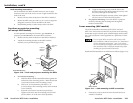
See figure 2-13 to wire a connector for the appropriate input
type. Use the supplied tie-wrap to strap the audio cable to the
extended tail of the connector. High impedance is generally
over 800 ohms.
LR
LR
Unbalanced Stereo Input
Balanced Stereo Input
(high impedance)
(high impedance)
Do not tin the wires!
Ring
Sleeve (s)
Tip
Sleeve
Tip
Sleeve
Tip
Tip
Ring
Figure 2-13 — Captive screw input connector
wiring
CAUTION
The length of the exposed (stripped) portion of the
copper wires is important. The ideal length is
3/16" (5 mm). Longer bare wires can short
together. Shorter bare wires are not as secure in the
direct insertion connectors and could be pulled out.
CAUTION
The captive screw audio connector can easily be
inadvertently plugged partially into one receptacle
and partially into an adjacent receptacle. This
misconnection could damage the audio output
circuits. Ensure that the connector is plugged fully
and only into the desired input or output.
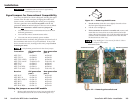
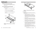
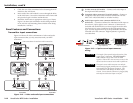
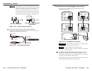
2. Cable the rear of the transmitter before fastening the AAP
module to the AAP frame.
3. Insert each of the AAP module’s screws through the holes
in the AAP frame. Secure the transmitter to the frame with
the provided captive washers and #4-40 nuts.
4. Install the AAP frame as appropriate to the type of frame.
Figure 2-11 shows the transmitter module being installed
in an AAP 102 wall mounting frame and the frame being
installed in a wall box.
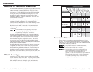
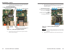
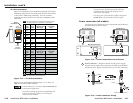
Panel Features and Connections
Transmitter input connections
Figure 2-12 shows all of the combinations of video and audio
input connectors that you may encounter with your MTP
transmitter.
Some transmitters do not have audio connections.
12V
0.5a
INPUT
MTP T AV RCA
OUTPUT
MAX
VIDEO
LR
INPUT
LR
12V
0.5a
MTP T AV
OUTPUT
MAX
VIDEO
12V
0.5a
INPUT
LR
MTP T SV A
OUTPUT
MAX
S-VIDEO
12V
0.5a
INPUT
MTP T SV A RCA
OUTPUT
MAX
S-VIDEO
LR
MTP T SV A RCA,
Rear Panel
MTP T AV RCA,
Rear Panel
MTP T AV AAP,
Front Panel
MTP T SVA AAP,
Front Panel
MTP T SV A,
Rear Panel
MTP T AV,
Rear Panel
AUDIO IN
S-VIDEO
IN
L
R
MTP T SVA
AUDIO IN
VIDEO
IN
LR
MTP T AV
21
21
4
4
2
1
3
3
44
Figure 2-12 — Video and audio input connections
2-132-12