


VersaTools
®
MTP Series • Installation
VersaTools
®
MTP Series • Installation
Installation, cont’d
If the transmitter and receiver are either older generation
units or jumper configured to the stereo audio position
(compatible with the older units), only a single device
needs to be powered in a two-unit system. See “Signal
Jumpers for Generational Compatibility” on page 2-2.
The device connected to the power supply, in turn,
provides power to its counterpart.
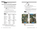
If the transmitter and receiver are separated by greater
than 500 feet (150 meters) of STP/UTP/FTP cable,
connect a power supply to both units regardless of the
model and jumper configuration.
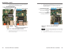
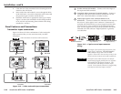
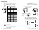
CAUTION
Power supply voltage polarity is critical. Incorrect
voltage polarity can damage the power supply and
the MTP. Identify the power cord negative lead by
the ridges on the side of the cord (figure 2-19).
CAUTION
The length of the exposed (stripped) copper wires is
important. The ideal length is 3/16" (5 mm).
Longer bare wires can short together. Shorter wires
are not as secure in the captive screw connectors
and could be pulled out.
Do not tin the stripped power supply leads before
installing the captive screw or direct insertion connector.
Tinned wires are not as secure in the captive screw and
direct insertion connectors and could be pulled out.
To verify the polarity before connection, plug in the power
supply with no load and check the output with a voltmeter.
The two power cord wires must be kept separate
while the power supply is plugged in. Remove
power before wiring.
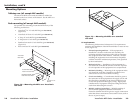
Use the supplied tie-wrap to strap the power cord to the
extended tail of the connector.
Your transmitter/receiver pair may have shipped with a
blue captive screw connector. This blue connector can be
plugged into either a blue or an orange power receptacle.
The blue connector does not have the extended tail or the
included tie-wrap.
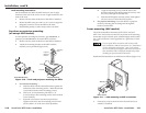
Alternatively, an optional Extron PS 123 Universal 12 VDC
Power Supply, part #60-814-01, can power multiple Extron
12 VDC devices using only one AC power connector.
7
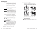
Power LED — Indicates power is applied to the MTP.
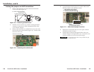
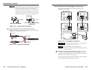
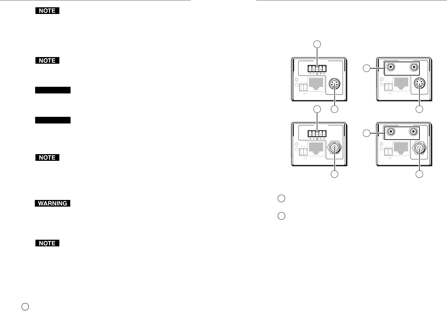
Receiver output connections
See figure 2-20 to identify the receivers’ rear panel output
connections. The figures show all of the combinations of
connectors that you may encounter with your MTP receiver.
MTP R AV RCA,
Rear Panel
MTP R AV,
Rear Panel
MTP R SV A RCA,
Rear Panel
MTP R SV A,
Rear Panel
OUTPUT
MTP R AV RCA
INPUT
VIDEO
12V
0.5a
MAX
L R
OUTPUT
MTP R SV A
L R
INPUT
S-VIDEO
12V
0.5a MAX
OUTPUT
MTP R SV A RCA
INPUT
S-VIDEO
12V
0.5a MAX
L
R
OUTPUT
MTP R AV
L R
INPUT
VIDEO
12V
0.5a MAX
9 9
10
11
8 8
10
11
Figure 2-20 — Output connector wiring
8
S-video connector (SV models) —
Connect an S-video device to
this 4-pin mini DIN connector.
9
Composite video connector (CV and AV models) — Connect a
composite video device to this BNC connector.
2-192-18