


VersaTools
®
MTP Series • Operation
Operation
VersaTools
®
MTP Series
A
Appendix A
Reference Information
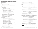
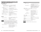
Specifications
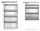
Part Numbers
3-2
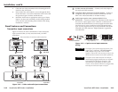
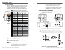
Front Panel Features
SHARP
C GAIN
Y GAIN
SHARP
GAIN
MTP R S-video Receiver
Front Panel
M
TP R Composite Video
R
eceiver Front Panel
2331231
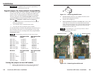
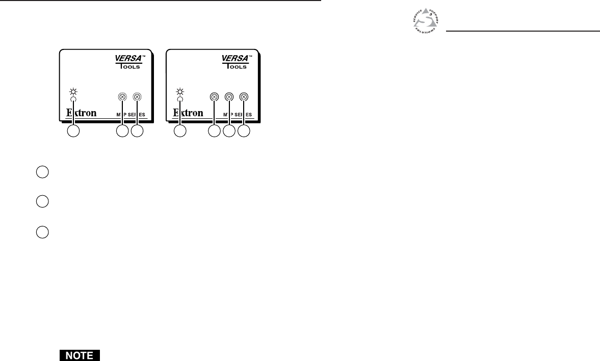
Figure 3-1 — MTP receiver front panels
1
Power LED — When lit, this LED indicates power is applied to
the MTP.
2
Sharpness — Adjusts the output image sharpness for long cable
runs.
3
Gain control — Adjusts the brightness of the output image to
compensate for long cable runs.
S-video receivers — There are separate controls for luminance
(Y) and chrominance (C) on S-video MTP receivers. If the
chrominance setting on the MTP receiver’s S-video output is too
low, the image may appear in monochrome. Adjust the S-video
gain until color appears.
Composite video receivers — There is only one gain control on
composite video MTP receivers.
All control knobs are removable to limit access if desired.
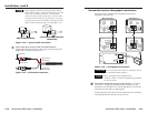
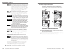
Troubleshooting — Skew Delay Compensation
CAT 5 TP cable can cause registration errors (in which
luminance leads or lags chrominance) between the Y and C
video signals on S-video transmitter/receiver pairs. Try using
the following methods to minimize or eliminate pair skew:
• Switch to Extron’s Enhanced Skew-Free A/V UTP cable.
• Add an S-video-to-BNC adapter and a skew
compensation cable equal to the length of pair skew to the
receiver’s output.
• Install an S-video-to-BNC adapter and an SEQ 100 BNC
Skew Equalizer on the receiver’s video output and adjust
the skew for the leading video image.