


VersaTools
®
MTP Series • Installation
VersaTools
®
MTP Series • Installation
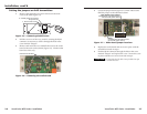
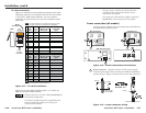
Installation, cont’d
2-152-14
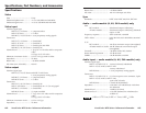
When making connections for the MTP from existing
audio cables, see figure 2-14 to identify the tip, ring, and
sleeve wires in various connectors. A mono audio
connector consists of the tip and sleeve. A stereo audio
connector consists of the tip, ring and sleeve. The ring,
tip, and sleeve wires are also shown on the captive screw
audio connector diagrams, figure 2-13 and figure 2-21.
Tip (+)
Sleeve ( )
RCA Connector (Mono)
Sleeve ( )
Ring (R)
Tip (L)
3.5 mm Stereo Plug Connector
(unbalanced)
Figure 2-14 — Typical audio connectors
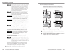
4
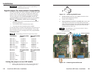
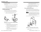
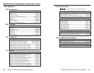
Audio input RCA connectors (RCA and AAP models) —
Connect an unbalanced stereo audio source to these L(eft) and
R(ight) RCA connectors (figure 2-15).
Sleeve (Gnd )
Right Channel
(Red Jacket)
Left Channel
(White Jacket)
Tip (Signal)
Figure 2-15 — RCA audio connectors
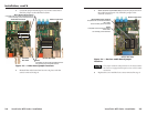
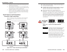
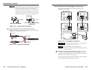
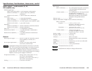
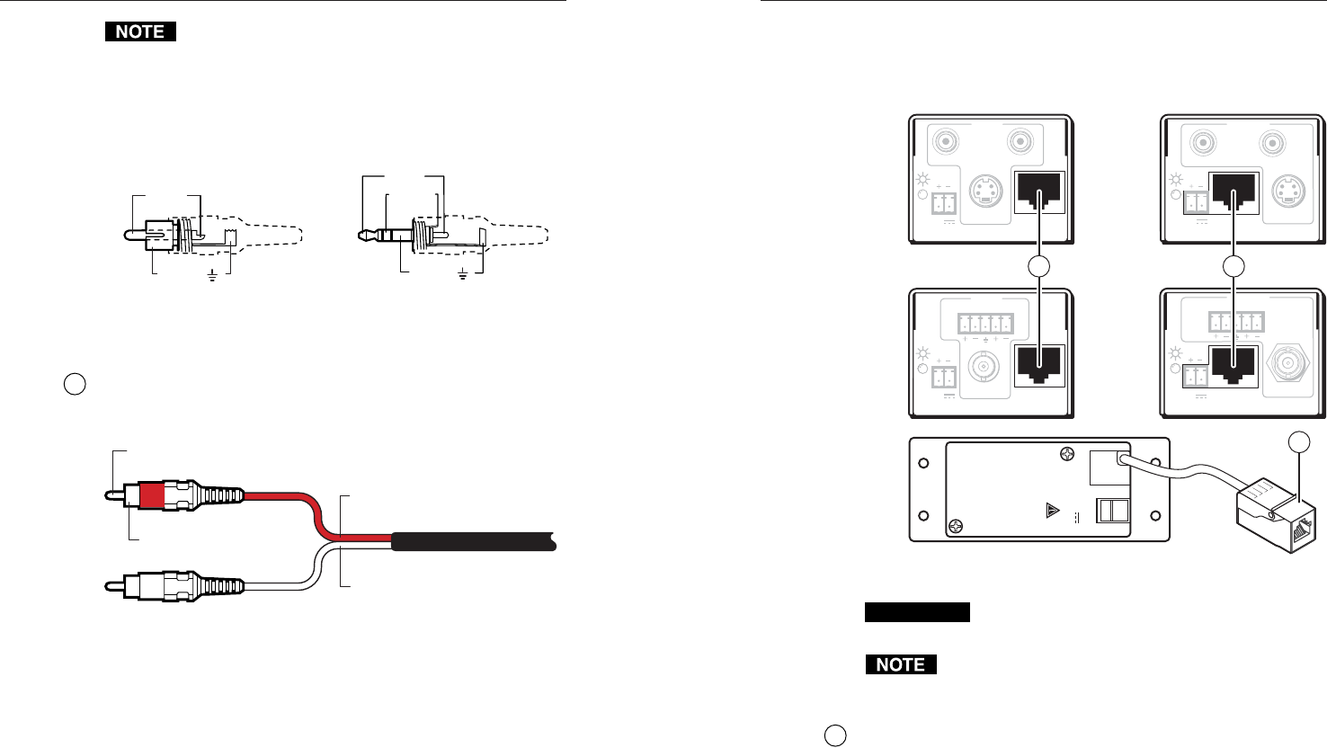
Transmitter/receiver throughput connections
See figure 2-16 to identify the connections between the
transmitter and receiver.
12V
0.5A
MAX
OUTPUT
POWER
− +
MTP Transmitters MTP Receivers
INPUT
LR
MTP T AV
OUTPUT
VIDEO
12V
0.5a
INPUT
MTP T SV A RCA
OUTPUT
MAX
12V
0.5a MAX
S-VIDEO
LR
OUTPUT
MTP R SV A RCA
INPUT
S-VIDEO
12V
0.5a
MAX
OUTPUT
MTP R AV
LR
INPUT
VIDEO
12V
0.5a MAX
R
L
5 5
5
Figure 2-16 — Throughput connections
CAUTION
Do not connect these devices to a computer data or
telecommunications network.
RJ-45 termination must comply with the
TIA/EIA T 568A or TIA/EIA T 568B wiring standards
for all connections.
5
Transmitter output and receiver input connector — Connect
one end of a TP cable to this RJ-45 female connector on the
transmitter. On the MTP T SV A AAP and MTP T AV AAP, the
connector is at the end of a short pigtail.
Connect the free end of the same TP cable from the transmitter
to this RJ-45 female connector on the receiver.