


VersaTools
®
MTP Series • Installation
VersaTools
®
MTP Series • Installation
Installation, cont’d
2-16
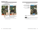
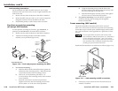
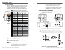
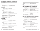
TP cable termination
Figure 2-17 details the recommended termination of TP cables
with RJ-45 connectors in accordance with the TIA/EIA T 568A
or TIA/EIA T 568B wiring standards. You can use either
standard, but ensure that you use the same standard on both
cable ends.
Side
RJ-45
Connector
Pin
1 Reserved
2 Reserved
3
Mono audio+ Mono audio+
4
Video-
6 Mono audio-
7
Reserved
8
Reserved
Mono audio-
Reserved
Reserved
wire
color
White-
green
Green
White-
orange
Blue
White-
blue
Orange
White-
brown
Brown
wire
color
568 A 568 B
Composite video
MTP signal
White-
orange
Orange
White-
green
Blue
White-
blue
Green
White-
brown
Brown
Chroma (C)+
Chroma-
Luma+
Luma-
S-video MTP
signal
Video+
Pin
1 Video+
2 Video-
3
Power+ Power+
4
5
Audio left-
6 Power-
7
Audio right +
8
Audio right -
Power-
Audio right +
Audio right -
wire
color
White-
green
Green
White-
orange
Blue
White-
blue
Orange
White-
brown
Brown
wire
color
568 A 568 B
Composite video
MTP signal
White-
orange
Orange
White-
green
Blue
White-
blue
Green
White-
brown
Brown
Luma (Y)+
Luma-
Chroma+ & audio left
+
Chroma- & audio left-
S-video MTP
signal
NOTE If you are using Enhanced Skew-Free™ A/V cable,
use the TIA/EIA T 568A standard only.
Audio left+
NOTE The signal depends on the position of the signal jumpers.
See “Signal Jumpers for Generational Compatibility” .
Jumpers in Mono position (defaul
t)
Jumpers in Stereo position
12345678
Insert
Twisted
Pair Wires
Pins:
5
Figure 2-17 — TP cable termination
When you are using Enhanced Skew-Free™ A/V cable, use
only the TIA/EIA T 568A standard.
Enhanced Skew-free A/V cable is not recommended for
Ethernet/LAN applications.
This cable is specially designed for compatibility with
Extron’s Twisted Pair products, wired using the
TIA/EIA 568 A standard.
The green, brown, and blue pairs of this cable have
virtually identical lengths and should be used to
transmit the video signals.
The orange pair of this cable has a different length and
should not be used to transmit the video signals.
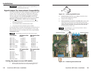
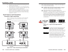
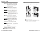
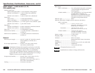
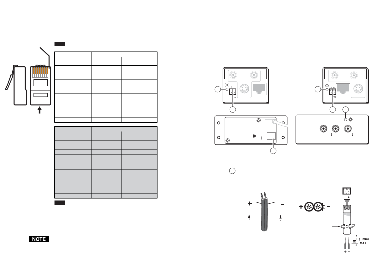
Power connection (all models)
See figure 2-18 to identify the power connections and indicators
and to identify the panel screws.
MTP Transmitters MTP Receivers
MTP AAP Transmitters
INPUT
MTP T SV A RCA
OUTPUT
S-VIDEO
LR
OUTPUT
MTP R SV A RCA
INPUT
S-VIDEO
R
L
12V
0.5a
MAX
12V
0.5a
MAX
AUDIO IN
VIDEO
IN
L
R
MTP T AV
12V
0.5A MAX
OUTPUT
POWER
− +
6 7
6
6
7 7
Figure 2-18 — Power connections and indicators
6
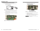
Power connector — Plug the external 12 VDC power supply
into this 2-pole captive screw connector on both the transmitter
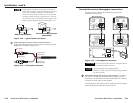
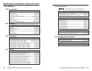
and the receiver. Figure 2-19 shows how to wire the connectors.
Power Supply
Output Cord
Captive Screw Connector
SECTION A–A
Ridges
Smooth
AA
Tie Wrap
3
5
Figure 2-19 — Power connector wiring
2-17