


2-7SW RGB and YUV A Switchers • Installation
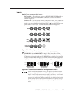
Inputs
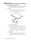
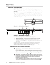
1
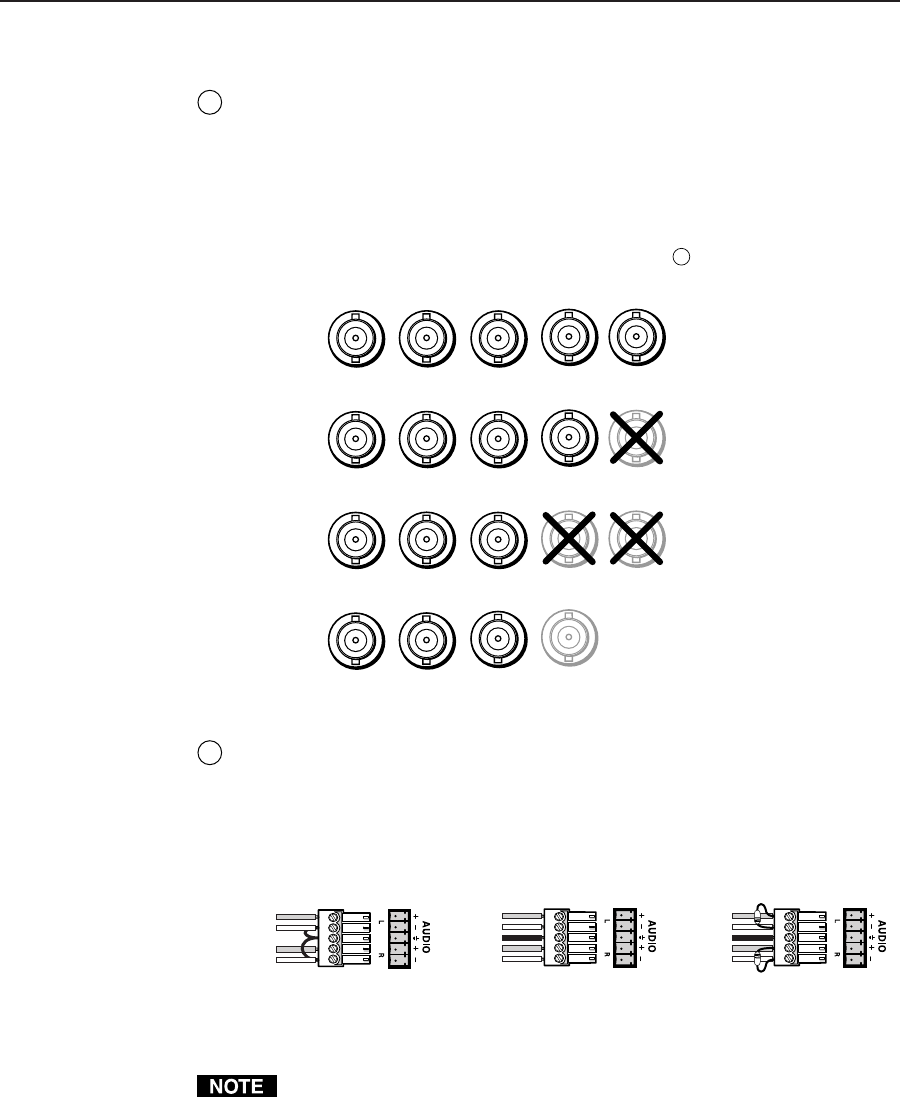
RGB and component video inputs —
RGB models — For each input, connect an RGBHV, RGBS, RGsB, RsGsBs, or
component video source to these BNC connectors. Connect the cables as
shown in figure 2-8.
SW6 YUV A — For each input, connect a component video, RGsB, or RsGsBs
source to one of these BNC connectors. If you are not switching digital
audio, you can use the Digital Audio input BNCs (
3
) for the composite sync
plane of RGBS video inputs. Connect the cables as shown in figure 2-8.
G
RGBHV
RGBS
RGsB,
RsGsBs
Component
Component
Video, RGsB,
RsGsBs, RGBS
B
H/HV
V
RG
B
H/HV
V
RG
B
H/HV
V
R-Y
Y
B-Y
Digital Audio
Figure 2-8 — Video input and output connections
2
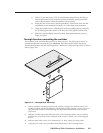
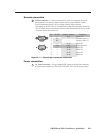
Balanced or unbalanced audio input connections (SW2 RGBHV A,
SW4 RGBHV A, and SW6 RGBHV A only) — Each input has a 3.5 mm,
5-pole captive screw connector for balanced or unbalanced stereo audio input.
Connectors are included with each SW RGBHV Series switcher, but you must
supply the audio cable. See figure 2-9 to wire a connector for the appropriate
input type and impedance level. High impedance is generally over 10k ohms.
Unbalanced Input
Tip
Sleeve
Tip
Sleeve
Balanced Input
Tip
Ring
Sleeve (s)
Tip
Ring
Tip
Ring
Sleeve (s)
Tip
Ring
Balanced Input
(high impedance)
(high impedance) (600 ohms)
600 ohms
600 ohms
Figure 2-9 — Captive screw connector wiring for audio inputs
Figure 2-9 shows three methods of wiring the captive screw audio connectors
for input, and figure 2-10 shows two methods of wiring the connectors for
output. A mono audio connector consists of the tip and sleeve. A stereo audio
connector consists of the tip, ring and sleeve. If wiring a captive screw
connector from an existing unbalanced audio cable, the white insulated wire is
typically the left channel (tip) and the red insulated wire is typically the right
channel (sleeve). There is no reliable standard for existing balanced audio
cables.