


QS-1SW RGB and YUV A Switchers • Quick Start
Quick Start — SW RGB and YUV A Switchers
Installation
Step 1 — Remove power
Turn off power to the input and output devices,
and remove the power cords from them.
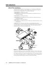
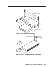
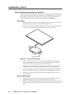
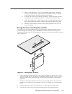
Step 2 — Mounting
SW2 —
If desired, mount the switcher in a rack using an
Extron 1U Universal Rack Shelf, part # 60-190-01.
If desired, mount the switcher under a desk using
an Extron Under-desk Mount Kit, part #70-077-01.
If desired, mount the switcher through a desk using
an Extron Through-desk Mount Kit, part #70-077-02.
SW4 or SW6 —
If desired, mount the switcher in a rack with the
supplied rack ears.
If desired, mount the switcher under a desk using
an Extron 1U Under-desk Mount Kit,
part #70-222-01.
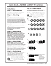
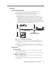
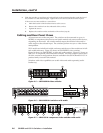
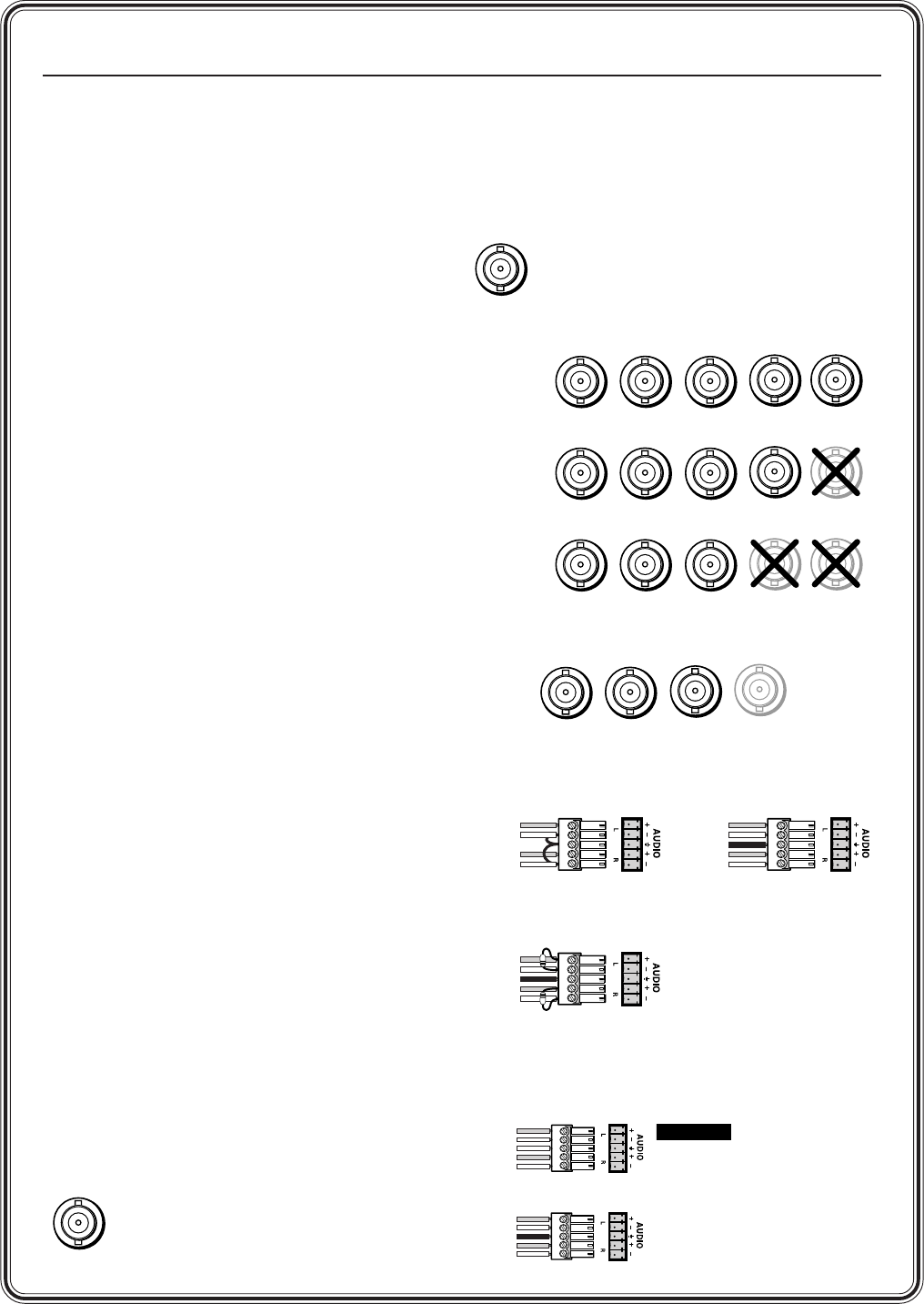
Step 3 — Video Inputs
RGBHV Models — Connect up to 2, 4 or 6
RGBHV, RGBS, RGsB, or RsGsBs video or compo-
nent video inputs to the Input connectors (3a).
SW6 YUV A — Connect up to 6 component video
or RGsB, RsGsBs video inputs to the Input connec-
tors (3b). If you are not switching digital audio,
you can use the Digital Audio BNCs for the
composite sync planes of RGBS video inputs.
Step 4 — Video Output
RGBHV Models — Connect an RGBHV, RGBS,
RGsB, or RsGsBs video or component video
display or other device to the Output connectors (3a).
SW6 YUV A — Connect a component video, RGsB,
or RsGsBs video display or other device to these
BNC connectors (3b). If you are not switching
digital audio, you can use the Digital Audio output
BNC to output the sync planes of RGBS video.
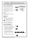
Step 5 — Audio Inputs
SW2 RGBHV A / SW4 RGBHV A / SW6 RGBHV A:
Cable audio models for stereo audio input (5).
High impedance is generally over 10 k ohms.
SW6 YUV A: Each input has a female BNC
connector for a digital audio input. If
you are not switching digital audio, you
can use this connector to input the
composite sync plane of RGBS
video.
R-Y
Y
B-Y
Digital Audio
3b
G
RGBHV
RGBS
RGsB,
RsGsBs,
Component
B
H/HV
V
RG
B
H/HV
V
RG
B
H/HV
V
3a
Unbalanced Input
Tip
Sleeve
Tip
Sleeve
Balanced Input
Tip
Ring
Sleeve (s)
Tip
Ring
Tip
Ring
Sleeve (s)
Tip
Ring
Balanced Input
(high impedance) (high impedance)
(600 ohms)
600 ohms
600 ohms
5
Unbalanced Output
Tip
See caution
Sleeve
Tip
See caution
Balanced Output
Tip
Ring
Sleeve (s)
Tip
Ring
6
CAUTION
Connect the sleeve
to ground.
Connecting the
sleeve to a negative
(-) terminal will
damage the audio
output circuits.
Digital Audio
Step 6 — Audio Outputs
SW2 RGBHV A / SW4 RGBHV A / SW6 RGBHV A:
Cable audio models for stereo audio output (6).
SW6 YUV A: Connect a digital audio device to this
female BNC connector for a digital audio
output. If you are not switching digital
audio, you can use this connector to
output the composite sync plane
of RGBS video.
Digital Audio