


3-3SW RGB and YUV A Switchers • Operation
Audio controls and indicators
3
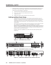
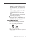
Audio configuration/save button and LED — The Audio button and LED
enable the user to view and/or change the current audio level setting for each
input. See Audio gain and attenuation in this chapter.
4
Down ( ) button and LED — The button is used to decrease the audio
level for a selected input. The LED flashes each time the button is pressed to
indicated a 1 dB decrease in the audio level. See Audio gain and attenuation in
this chapter.
On the SW2 RGBHV A, this button and LED are secondary functions of the
Input 1 button and LED. On the SW6 RGBHV A, this button and LED are
secondary functions of the Input 5 button and LED.
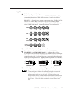
5
Up ( ) button and LED — The button is used to increase the audio level
for a selected input. The LED flashes each time the button is pressed to
indicated a 1 dB increase in the audio level. See Audio gain and attenuation in
this chapter.
On the SW2 RGBHV A, this button and LED are secondary functions of the
Input 2 button and LED. On the SW6 RGBHV A, this button and LED are
secondary functions of the Input 6 button and LED.
6
–dB/+dB LEDs — The –dB and +dB LEDs indicate the polarity of the audio
level setting. See Audio gain and attenuation in this chapter.
7
Audio level indicators (SW4 RGBHV A and SW6 RGBHV A only) — The
Input 1 through Input 4 LEDs indicate a range of 6 dB when lit (Input 1 LED
off = 0 dB to 5 dB, Input 1 LED lit = 6 dB to 11 dB, Input 2 LED lit = 12 dB to
17 dB, and so on). See Audio gain and attenuation in this chapter.
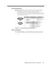
Autoswitch mode control and indicator
When autoswitching is enabled, the switcher continuously monitors all inputs and
automatically switches to the highest-numbered input with video sync pulses
present. If video is absent from all inputs, no input is selected.
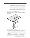
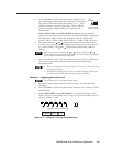
8
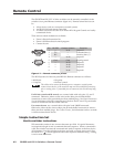
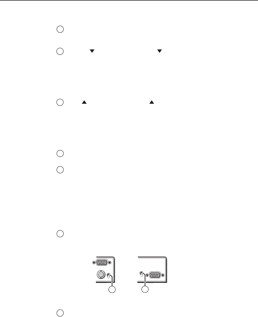
Auto/Manual switch — The rear panel Auto/Manual toggle switch
(figure 3-3) selects autoswitching mode or manual switch mode.
REMOTE
SW4 and SW6
Models
SW2 Models
AUTO
MANUAL
AUTO
MANUAL
REMOTE
V
H/HV
8
8
Figure 3-3 — Rear panel Auto/Manual switch
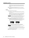
9
Auto Switch Active LED — When lit, the front panel Auto Switch Active LED
indicates that the switcher is in autoswitch mode. When unlit, the switch is in
normal (manual) mode.