


Operation, cont’d
SW RGB and YUV A Switchers • Operation3-2
Operation
Controls and Indicators
The SW RGB or SW YUV A family of switchers have 2, 4, or 6 input buttons and
LEDs on the front panel. Audio models also have front panel configuration
controls and LEDs. All models have an Auto/Manual mode selection switch on the
rear panel.
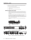
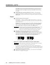
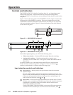
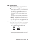
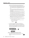
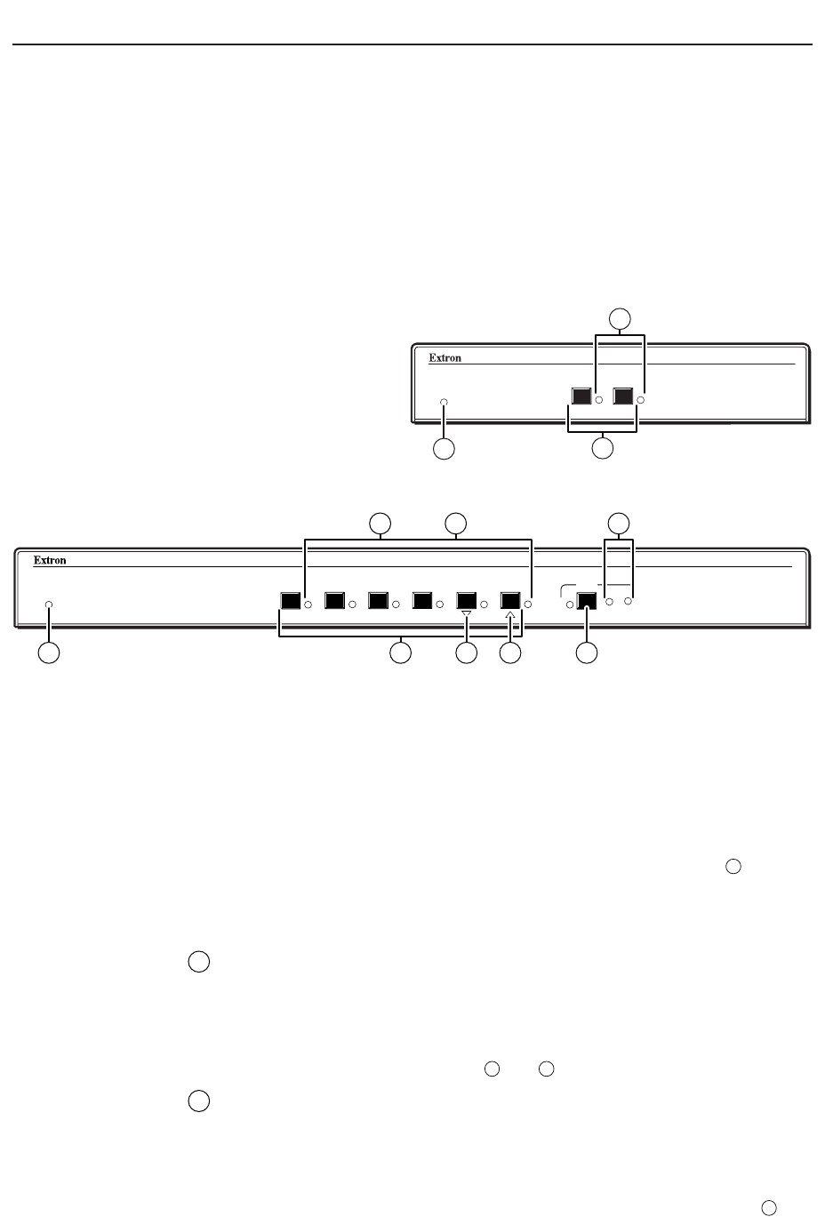
Figure 3-1 shows the front panel of an SW2 RGBHV switcher. Figure 3-2 shows the
front panel of an SW6 RGBHV A switcher. These two examples show all of the
combinations of button combinations and enclosure sizes that you may encounter
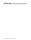
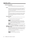
with your particular switcher. Figure 3-3 shows the location of the Auto/Manual
switch on the rear panel.
SW2 RGBHV
RGBHV & AUDIO SWITCHER
AUTO SWITCH
ACTIVE
2
1
9
2
1
Figure 3-1 — SW2 RGBHV front panel
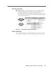
SW6 RGBHV A
RGBHV & AUDIO SWITCHER
AUDIO
CONF/SAVE
6
5
4
32
1
AUTO SWITCH
ACTIVE
-dB
+dB
9
6
3
72
1
4 5
Figure 3-2 — SW6 RGBHV A front panel
In the following descriptions, you will find the following terms:
• Video-only switcher — Switches RGB video only. No audio switching.
• Analog audio switcher — Switches analog audio on captive screw
connectors as well as RGB video. This type of switcher does not include the
SW6 YUV A.
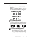
On audio switchers, two of the input buttons and LEDs have dual functions.
Double function controls on figure 3-1 and figure 3-2 have two callouts (
n
numbers), each indexed to a function in the following pages.
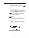
Input selection controls and indicators
1
Input buttons — When pressed, each input button selects the associated
input for output.
On some audio-switching models, the rightmost input buttons (Input 1 and
Input 2 on SW2 models and Input 5 and Input 6 on SW6 models) are also used
to decrease and increase the amount of audio gain for a selected input. See
Audio controls and indicators, items
4
and
5
.
2
Input LEDs — When lit, the input LEDs identify the selected input. If audio
is broken away (available under RS-232 control only), the selected video input
is indicated by a steadily lit input LED, and the selected audio input is
indicated by a blinking input LED.
On the SW4 RGBHV A and SW6 RGBHV A, the input LEDs also indicate the
audio level of the selected input. See Audio controls and indicators, item
7
.