


3-4 User’s Reference Guide
Netopia R9100 Ethernet Router status lights
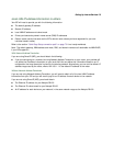
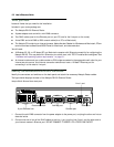
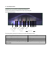
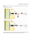
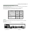
The figure below represents the Netopia R9100 status light (LED) panel.
Netopia R9100 LED front panel
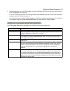
The following table summarizes the meaning of the various LED states and colors:
When this happens... the LEDs...
The Ethernet WAN interface is operational 3 is green.
The Ethernet WAN interface detects a collision 3 flashes orange.
In normal operation 4 is off.
When data is transmitted or received over the Ethernet link 4 flashes yellow.
Note: 2, 5, 8 – 11 are unused. Also, Console carrier (6) is ignored if the console is not configured for a
remote modem.
2 3 4 5 6 7 8 9 10 11 12 13 14 15 16171819 20 21
Management
Ready
Channel 1
Link/Receive
Console
Auxiliary
Collision
Traffic
WAN 1 WAN 2 Ethernet
Power
1
Channel 2
Management
Ready
Channel 1
Channel 2