RESTRICTED USE ONLY Fargo Electronics, Inc.
DTC400/DTC300/DTC300M Card Printer User Guide (Rev. 1.1)
9-3
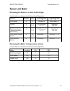
Sensor and Motor
Reviewing the Sensor Location and Voltages
Use this table as a reference tool for Board Level Diagnostics
Sensor Location
Pin Low Range VDC High Range VDC
RFID Board J5 3 Present .02 Not Present .70
Headlift J9 1, 3
(+, -)
Not Depressed
0 - .17
Depressed
4.9 – 5.5
Print Cover Sensor
(Sensor mounted to
Main Board)
J4 1, 2
(+, -)
Not Depressed
0 - .17
Depressed
4.9 – 5.5
Print Ribbon Encoder
Sensor
J4 3,4
(+, -)
Unblocked 0 -.17 Blocked 4.9 – 5.5
Card Detection
Sensor
J4 Unblocked 0 -.17 Blocked 4.9 – 5.5
Reviewing the Motor Voltages (when active)
Use this table as a reference tool for Board Level Diagnostics
Motor Location Pin VDC
Print Drive Stepper J3 4 4
Print Headlift J20 6 17.0
Ribbon Drive J20 8 5


