


Pin Assignments
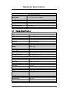
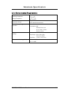
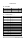
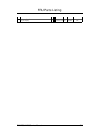
B.7 DC-IN Jack Pin Assignment
The pin assignment of the DC-IN connector is as follows:
No Signal Description Type
1 ADAPV+ Adapter input voltage I
2 Gnd Ground O
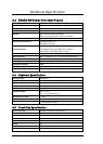
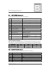
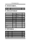
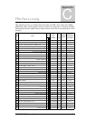
B.8 LCD Connector Pin Assignment
The pin assignment of the LCD connector is as follows:
NO. Signal Description Type
22 INVENA
Flat panel backlight signal
control the LCD backlight.
O
2 LCDID0 LCD type bit0 I
4 LCDID1 LCD type bit1 I
6 LCDID2 LCD type bit2 I
8 LCDID3 LCD type bit3
20 BRIGHTNESS LCD brightness adjust voltage O
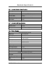
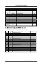
23 TXOUTU0- O
21 TXOUTU0+ O
17 TXOUTU1- O
15 TXOUTU1+ O
11 TXOUTU2- O
9 TXOUTU2+ O
5 TXCLK- O
3 TXCLK+ O
16 MAIL LED
10 LED GREEN
12 LED AMBER
14 LED CHG
46,48,50 +3V
24,26,28,30,32 +5V
1,7,13,19,25,31,37,43,49,34,36,38,
40,42,44
GND
18 NC
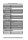
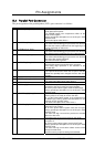
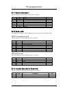
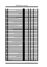
B.9 HDD Pin Assignment
The pin assignment of the internal HDD is as follows:
NO. Signal Description Type
1 HDDRESET# Reset primary disk O
35 RPDA0 Primary disk address 0 O
33 RPDA1 Primary disk address 1 O
36 RPDA2 Primary disk address 2 O
17 RPDD0 Primary disk data 0 I/O
15 RPDD1 Primary disk data 1 I/O
13 RPDD2 Primary disk data 2 I/O
11 RPDD3 Primary disk data 3 I/O
9 RPDD4 Primary disk data 4 I/O
7 RPDD5 Primary disk data 5 I/O
5 RPDD6 Primary disk data 6 I/O
FIC M295 / M296 Service Manual B-5