


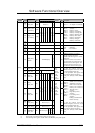


Software Functional Overview
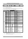
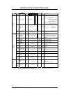
Register Bit Number
Function Address
Name
R/W
7 6 5 4 3 2 1 0
Logic
De-
fault
Description
E0h PMU_CONT R/W RES[7:3]
E
C
_
R
E
G
B
A
Y
_
L
E
D
P
O
W
_
L
E
D
- 0x00
EC_REG =1
BAY_LED
=1:
POW_LED
=1:
PMU does not initialize
E
register when system
power is off.
PMU indicates the Batter
y
discharge status to the
LED_BAY#n, when the
battery is installed.
The Power LED blink
E1h
ACPI_ACC_
ENB
R/W RES [7:1]
O
S
_
S
T
S
- 0x00
OS_STS = 1:
= 0:
ACPI mode
Legacy mode
PMU
control
E2h OFF_TIME R/W DATA [7:0] - 0x64
Power switch over ride function timer
01h-FFh (0.1-25.5esc step 0.1sec)
00h : Reserved
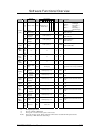
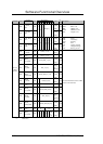
E3h
POLLING_
ADDRESS
R/W Slave Address [6:0]
R
E
S
0x00
Address: 0x00-0x7F
The polling slave address setting
If this address is 00, the Polling is
disabled.
E4h
HIGH_
ALARM
R/W DATA [7:0]
Signed
value
0x00
If the received data GE this value, the
event will be detected.
E5h
LOW_
ALARM
R/W DATA [7:0]
Signed
value
0x00
If the received data LE this value, the
event will be detected.
E6h
POLLING_
INTERVAL
R/W DATA [7:0] 0x00
0x00 :Polling disable
0x01 – 0xFF [x 250ms] (250ms to
63.75sec)
E7h
POLLING_
DATA
R(/W) DATA [7:0]
Signed
value
0x00
This register shows data at latest
polling.
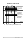
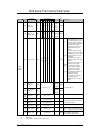
E8h
HARDWARE_
SHUT_DOWN
R/W DATA [7:0]
Signed
value
0x7D
If the thermal sensor read value GE
this value, the PMU automatically off
the power.
E9h
POLLING_
COMMAND
R/W DATA [7:0] 0x00
Polling command (data register)
address.
EAh
RETRY_
COUNT
R/W DATA [7:0] 0x10
0x00 - 0xFF: Retry count value (0-
255)
Thermal
Sensor
Polling
EBh
To Reserved R/W Don't care
EFh
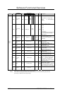
F0h
BURST_FLG_
CLR
R/W DATA [7:0] - -
After writing to the register addressed
A8h-AFh,
Set the 00h to this register.
PMU
control
F1h
To
FFh
Reserved R/W Don't care
R(/W): This is the read only register, but the written data will be able to read back till PMU updates the data
periodically, or PMU detects the status change.
FIC M295 / M296 Service Manual 3-43