


FS-8700-17 Optomux Driver Manual
FieldServer Technologies 1991 Tarob Court, Milpitas, California 95035 (408) 262-2299 fax: (408) 262-9042
Visit our website: www.fieldserver.com E-mail: support@fieldserver.com
Page 14
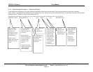
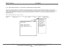
4.4.8 Map Descriptor Example 5 – Using Address and Length to tell the FieldServer which module positions to access.
This example shows a map descriptor which reads analog inputs from an Optomux Device. The address and length tell the driver which inputs to
read. Take care to ensure that the data array used for storage has a data format suitable for storing the data type returned by the command. In
this case an unsigned integer at least 16 bits long ( eg UINT16 or FLOAT). Also take care to ensure that you understand the scaling of the data
returned by the Optomux device. There are parameters that you can add to a map descriptor to have the driver scale the value. This is discussed
in the FieldServer Configuration Manual.
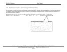
Map_Descriptor_Name, Data_Array_Name, Data_Array_Offset, Function, Node_Name, Address, Length, Scan_Interval, opto22_function
DEVICE77_STAT , ANA_DATA , 0 , rdbc , DEV77 , 2 , 15 , 1.0s , READ ANALOG INPUTS
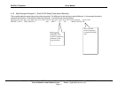
Data read from the
Optomux Device is
placed in this array.
Starting at this array
position.
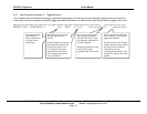
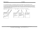
The first module
position that is read
is position 2.
Module positions
are numbered 1 to
16.
Data from 15
module positions
must be read. Thus
starting at 2, the last
module position
read is 16.
This is the Optomux
Driver function that
must be performed.