


FS-8700-40 SBT FSI Driver Manual Page 6 of 29
FieldServer Technologies 1991 Tarob Court Milpitas, California 95035 USA Web: www.fieldserver.com
Tel: (408) 262 2299 Fax: (408) 262 2269 Toll Free: (888) 509 1970 email: support@fieldserver.com
4 CONFIGURING THE FIELDSERVER AS A SBT-FSI CLIENT
For a detailed discussion on FieldServer configuration, please refer to the FieldServer Configuration Manual. The
information that follows describes how to expand upon the factory defaults provided in the configuration files
included with the FieldServer (See “.csv” sample files provided with the FieldServer).
This section documents and describes the parameters necessary for configuring the FieldServer to communicate
with a SBT-FSI Server.
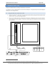
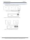
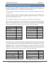
In FSI mode, the NIM-1R or NIM-1W or RPM allows the FieldServer to gather data from up to 63 MXL/XLS Panels
connected via an MXL/XLS network. The default configuration shipped with the FieldServer will monitor two
panels (1 and 2) with 8 modules (1 to 8) each.
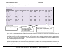
When the FieldServer is configured as a Client, two sets of data are collected by a “poller” Map Descriptor.
The first is a collection of 19 counters per panel. Each 16-bit counter is incremented by the poller Map Descriptor
whenever the corresponding event occurs. An external Client can read these counters to quickly determine
whether a new event has been reported to the Server. The counters are mapped into the Data Array specified for
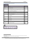
the poller Map Descriptor. Counter offsets into the Data Array per event type are indicated below:
Event Counter Offset
Fire Alarm In 0
Fire Alarm Out 1
Fire Alarm Acknowledge 2
Trouble In 3
Trouble Out 4
Trouble Acknowledge 5
Supervisory In 6
Supervisory Out 7
Supervisory Acknowledge 8
Security Alarm In 9
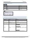
Event Counter Offset
Security Alarm Out 10
Security Alarm Acknowledge 11
Status In 12
Status Out 13
Test In 14
Test Out 15
Audible Silenced 16
Audible Unsilenced 17
System Reset 18
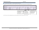
The second set of data is a collection of bit maps that can be queried to identify the device that has reported the
event. When an alarm event arrives from a device, the corresponding bit is set in two separate arrays. The bit in
one array indicates the alarm has occurred, and the bit in the other array indicates that the alarm has not yet been
acknowledged. When an “alarm clear” event arrives, the bit in the alarm array is cleared. If an “alarm
acknowledge” event arrives, the bit in the un-acknowledged array is cleared. All event arrays in a Client driver
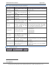
configuration are optional. To enable an event array, a Map Descriptor must be defined in the configuration using
a Map Descriptor message type that corresponds to the array as shown in the following table:
Array
Msg_Type
Fire Alarm Fire
Fire Alarm Un-Acknowledged Fire_Ack
Trouble Alarm Trouble
Trouble Un-Acknowledged Trouble_Ack
Supervisory Alarm Super
Supervisory Un-Acknowledge Super_Ack
Array
Msg_Type
Security Alarm Secur
Security Alarm Un-Acknowledged Secur_Ack
Status Status
Test Test
Audible (Un)Silenced Audible
System Reset Reset