


2. INSTALLATION
Page 7 © 2007 DH Instruments, a Fluke Company
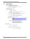
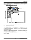
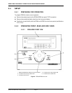
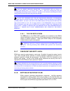
Each of the three components of the PGC-10000-AF system has its own Operation and Maintenance
Manual and individual setup and start up instructions. Figure 1 shows the typical setup configuration of a
complete PGC-10000-AF system.
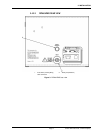
Figure 1. Typical PGC-10000-AF installation layout
2.3 SITE REQUIREMENTS
The RPM4/HPMS A70M/A20M-AF is usually delivered as part of an PGC-10000-AF pneumatic gauge
calibrator. The PGC-10000-AF also includes a GPC1-10000-AF and a GB-152-AF that each have their
own Operation and Maintenance Manual. See the GPC1 and GB-152 Operation and Maintenance
Manuals for information on their site requirements. Also see Section 2.2 for information on setup of a
complete PGC-10000-AF system.
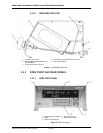
Install RPM4 on a flat, stable surface at a convenient height. The front feet can be extended so that the
unit can be inclined for easier viewing. Consider the placement of the FOOT SWITCH which may need to
be accessed frequently while running calibrations.
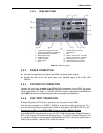
Support facilities required for RPM4/HPMS A70M/A20M-AF include an electrical power source of 85 to
264 VAC, 47 to 440 Hz.
CAUTION
GB152 Pressure Generation Component
GB152 Setting
CAUTION
GPC1-10000-AF
Gas Pressure Controller
RPM4/HPMS A70M/A20M Reference Pressure Monitor
GB152-AF Gas
Booster
GB152-AF
Drive Air Control Kit
Remote ENTER Footswitch
CAUTION
GB152 Pressure Generation Component
GB152 Setting
CAUTION
GPC1-10000-AF
Gas Pressure Controller
RPM4/HPMS A70M/A20M Reference Pressure Monitor
GB152-AF Gas
Booster
GB152-AF
Drive Air Control Kit
Remote ENTER Footswitch