4. REMOTE OPERATION
Page 73 © 2007 DH Instruments, a Fluke Company
4
4
.
.
R
R
E
E
M
M
O
O
T
T
E
E
O
O
P
P
E
E
R
R
A
A
T
T
I
I
O
O
N
N
4.1 OVERVIEW
Most of the RPM4 front panel functions can also be executed by commands from a remote computer.
The host computer can communicate to the RPM4 using the RPM4’s COM1 RS232 port or it’s IEEE-488 port.
Before writing code using RPM4 remote commands, familiarize yourself with its operating principles by
reviewing Section 3 of this manual.
4.2 INTERFACING
Sending a program message to the RPM4 places it into remote mode. The remote indicator to the right
of the display window lights when the RPM4 is in remote mode. It also flickers when a program message
is received. The menus usually accessed from the front panel are locked out while in remote. The [ESC]
key returns the RPM4 to local operation unless the <REMOTE> program message, which locks out all
keypad operation, was sent to the unit.
4.2.1 RS232 INTERFACE
4.2.1.1 COM1
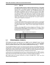
The RPM4 COM1 RS232 interface is located on the back of the unit. It is a 9-pin
male DB-9F connector configured as a DCE device. Data is transmitted out of
the unit using pin 2, and is received on pin 3. This allows a normal pin-to-pin
DB-9M to DB-9F RS232 cable to be used to connect to a DTE host.
Handshaking is not required or supported. The COM1 receive buffer is
80 bytes deep. If you overflow the buffer by sending too much data, the data will
be lost. Because of this, you must send a single program message at a time
and you must wait for the RPM4 to reply from the previous command before
issuing another command.
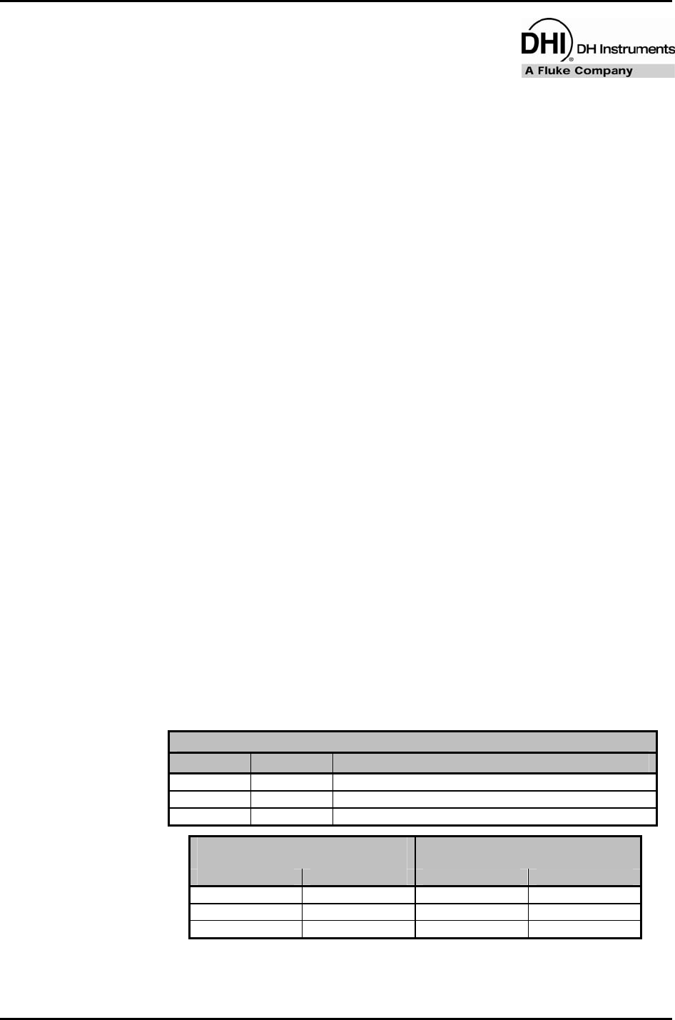
Table 12. COM1 pin designations and connections
RPM4 COM1 DB-9F PIN DESIGNATIONS
PIN # FUNCTION DESCRIPTION
2 TxD This pin transmits serial data from the RPM4 to the host.
3 RxD This pin accepts serial data from the host computer.
5 Grn This pin is the common return for the TxD and RxD signals.
IBM PC/XT DB-9F
CONNECTIONS
IBM PC/XT DB-9M TO RPM4 DB9F
CONNECTION
DB-25M DB-9F DB-9M DB-9F
2 3 3 3
3 2 2 2
7 5 5 5


