


2
22
2
3(5$7,21
3(5$7,213(5$7,21
3(5$7,21
5(027(&
5(027(&5(027(&
5(027(&21752/
21752/21752/
21752/
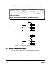
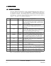
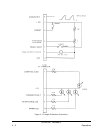
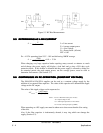
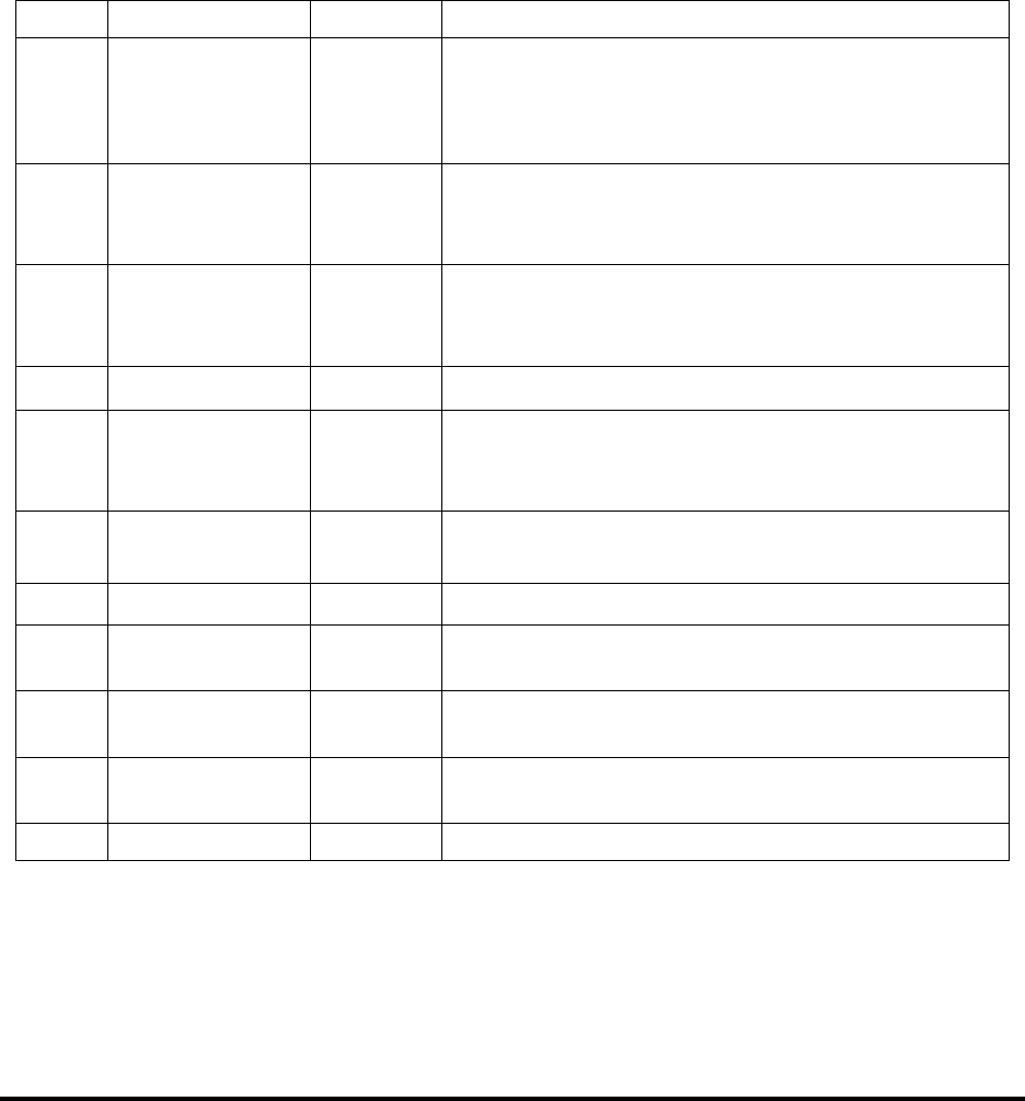
The Series 500A/102A/152A/202A is easily controlled through the remote connector on
the input panel of the unit. Only the ENABLE/RESET, V PROGRAM and GND signals
are required for operation. The remaining signals are provided for status monitoring and
fault diagnosis. A schematic diagram showing the suggested interface circuit is shown in
Figure 4-1. This table is for a standard configuration.
Indicates a shorted O/P or a very large load capacitor.OUTPUTLOAD FAULT2
Open collector. Indicates an output overvoltage.
Temperature fault or low input voltage condition.
OUTPUTSUMMARY
FAULT LED
3, 6
Open collector. Indicates that the power supply is
reaching end-of-charge, i.e. the V PROGRAM set point.
OUTPUTEOC LED13
Open collector. Indicates that the power supply is
receiving an INHIBIT signal.
OUTPUTINHIBIT LED15
Control circuit return. Also chassis/earth groundOUTPUTGND14
15V regulated. Can be used for user programming
applications 20mA max.
OUTPUT+15V9, 11
A +10 to 15V with respect to ground, disables the unit.
Open or ground allows operation. This input can be
used to disable charging during HV switch recovery.
INPUTINHIBIT10
0-10V analog of output charging voltage waveform.OUTPUTV
ANALOG
8
A 0-10V signal (with respect to ground) proportional to
the peak of the output charging voltage. Can be used to
drive a meter displaying peak output voltage.
OUTPUTV
PEAK
7
A 0-10V signal with respect to ground at this pin
programs the output voltage proportionally from zero to
rated output.
INPUTV PROGRAM5
A high signal (+10 to 15V) with respect to ground
(pin 14) will enable the power supply. Latching faults
can be cleared by cycling this switch. Ground or open
disables the supply.
INPUTENABLE/RESET1
DESCRIPTIONI/OSIGNAL NAMEPIN
Table 4.1 Control Interface Connection For Standard 500A/102A/152A/202A Series
83-493-001 Revision G
4 - 1 Operations