,
,,
,
1,7,$/
1,7,$/1,7,$/
1,7,$/
&+(&.287
&+(&.287&+(&.287
&+(&.287
3
33
3
52&('85(
52&('85(52&('85(
52&('85(
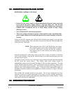
LETHAL VOLTAGES PRESENT
ONLY QUALIFIED PERSONNEL TRAINED IN THE SAFETY ASPECTS OF
HIGH VOLTAGE SHOULD PERFORM INITIAL CHECKOUT PROCEDURES.
The power supply should have no visible damage or defects and the cover should be
securely fastened. Properly connect the input power (Section 3.5), control connector
(Sec. 4.1) and HV output (Sec. 3.5, and 3.6).
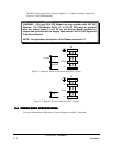
If there is no load connected, the power supply will regulate the output voltage to the
programmed voltage level or sense an open circuit and immediately shut down indicating a
FAULT.
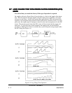
If there is a short circuit or overload condition on the output, the power supply will operate
in a 50% duty cycle protection mode and indicate a LOAD FAULT.
An overload condition can occur if the INHIBIT signal is missing, allowing HV switch to
latch-up. It can also occur if the discharge rep. rate is too high to allow the capacitor to
fully charge to V PROGRAM.
Double check all connections and ensure that all personnel are protected from the HV output.
With the V
PROGRAM
at zero volts, turn the power supply on in the following sequence:
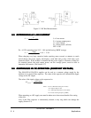
1. Connect power supply to the HV load
2. Increase load rep. rate to prevent a full charge
3. V
PROGRAM
signal (pin 5) at zero volts.
4. ENABLE/RESET signal (pin 1) at zero volts.
5. Assert ENABLE/RESET signal to 15V.
6. Verify HV output is at approx. zero volts.
7. Increase HV (by increasing V
PROGRAM
voltage) output slowly and verify adjustability.
8. Decrease load rep rate to allow full charge
83-493-001 Revision G
4 - 3 Operations


