0$,17(1$1&($1'&$/,%
0$,17(1$1&($1'&$/,%0$,17(1$1&($1'&$/,%
0$,17(1$1&($1'&$/,%
5$7
5$75$7
5$7
,21
,21,21
,21
6$)(7<35(&$87,216
6$)(7<35(&$87,2166$)(7<35(&$87,216
6$)(7<35(&$87,216
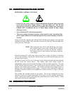
ONLY QUALIFIED PERSONNEL TRAINED IN THE SAFETY ASPECTS OF
HIGH VOLTAGE SHOULD PERFORM CALIBRATION.
The calibration steps described in this section require operation of the power supply with
the cover removed. Proceed with extreme caution as hazardous voltages are exposed
throughout the unit.
Safety glasses must be worn to prevent serious injury in the event of a component failure
(e.g., power transistors readily explode during fault conditions).
Because the power supply does not receive proper cooling with the cover removed, it must
be cooled by an external fan placed next to the supply to cool the inverter and HV section
(min. air flow 100 CFM (2.83 M
3
/min.)) when operating at full power. Operation at full
power with cover removed should be limited to less than five minutes.
0$,17(1$1&(
0$,17(1$1&(0$,17(1$1&(
0$,17(1$1&(
No maintenance is required under normal operating conditions. Occasional vacuum or
blow-out of the chassis may be required when operated in extremely dirty environments.
The oil-filled HV assembly must not be opened. The oil and components have been
specially cleaned and vacuum impregnated at the factory and the assembly hermetically
sealed. Opening assembly will compromise performance and void warranty. HV Tanks
must only be services at Lambda EMI.
&$/,%5$7,21
&$/,%5$7,21&$/,%5$7,21
&$/,%5$7,21
Calibration of the output voltage is accomplished with trim pot RP4 located on the control
board. This is the top PC board of the inverter assembly. RP4 is a 25 turn trimpot. Slowly
turn it clockwise to decrease the output voltage for a given V
PROGRAM
. Factory set for 10V
rated voltage for standard version. Refer to Sections 4.1 and 4.2 of product specification
for Linearity and Accuracy.
83-493-001 Revision G
6 - 1 Maintenance and Calibration


