0
00
0
($685,1*+
($685,1*+($685,1*+
($685,1*+
,*+9
,*+9,*+9
,*+9
2/7$*(6
2/7$*(62/7$*(6
2/7$*(6
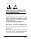
WARNING: EXTREME CAUTION MUST ALWAYS BE EXERCISED WHEN
TAKING ANY HIGH VOLTAGE MEASUREMENTS. IT SHOULD BE DONE
ONLY BY QUALIFIED PERSONNEL WHO ARE TRAINED IN THE SAFETY
ASPECTS OF WORKING WITH HIGH VOLTAGE.
A sample of the output voltage is available in the REMOTE connector. If it is desired to
measure the HV output externally, care must be taken to understand the accuracy of the
measurement.
When making a DC measurement, such as when the power supply is holding voltage on a
capacitor, any HV probe and DVM combination can be used. The Fluke 80K-40 probe
with any 10M input resistance DVM is adequate up to 40kV. Building a simple resistor
divider using appropriate HV resistors is also very straightforward. Keep in mind that all
HV resistors, including the one in the Fluke probe, exhibit a negative voltage coefficient,
changing by up to 4% from zero to max. voltage. Derating the resistors and calibrating at
the operating point solves this problem.
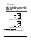
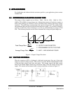
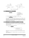
The value of the resistor R1 and R2 (Figure 5.3) can be calculated as follows:
where V
O
is the High Voltage being measured.V
M
=
R
2
R
1
R
2
V
O
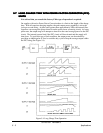
Making a pulsed measurement with an oscilloscope requires a compensated HV probe
having a wide bandwidth. Simply connecting a DC probe, through the proper resistance,
into a scope yields a slow response only adequate for low rep. rate systems. As with DC
probes, the pulsed probe resistor voltage coefficient is a problem. In addition, damage to
the resistors can occur during pulsing due to high electric field gradients. Also, stray
capacitance to nearby objects can significantly alter the pulse response. For a
high-performance, shielded probe to 40KV use a Tektronix P6015 or Ross Engineering
VD60-8.3-A-K-LB.
Measurements accurate to better than 0.1% can be achieved using a bias technique. For
example, if a 40V signal (40kV divided by 1000) is to be measured accurately, the minus input
of the DVM would be biased up 40V. The original signal, with respect to ground, is fed to the
plus input of the DVM. The bias can be measured accurately for absolute measurements, or
relative measurements read directly as the line or load is varied. In the same manner, an
oscilloscope return can be biased for accurate peak measurements during pulsing.
83-493-001 Revision G
5 - 3 Applications


