


/
//
/
21*&
21*&21*&
21*&
+$5*(7
+$5*(7+$5*(7
+$5*(7
,0(:
,0(:,0(:
,0(:
,7+3
,7+3,7+3
,7+3
2:(5)$&725&
2:(5)$&725&2:(5)$&725&
2:(5)$&725&
255(&7('3)&
255(&7('3)&255(&7('3)&
255(&7('3)&
81,76
81,7681,76
81,76
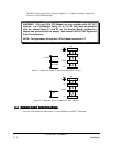
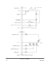
It is advised that you consult the factory if this type of operation is required.
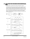
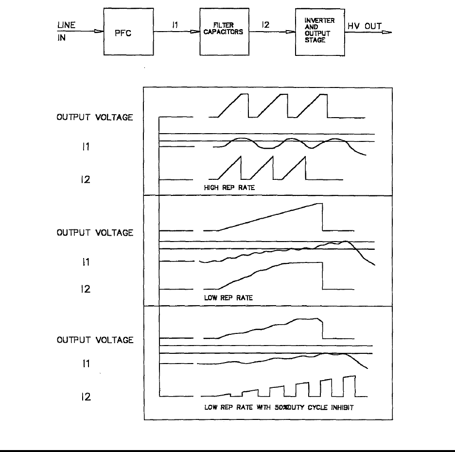
On supplies with active Power Factor Correction there is a limit to the length of the charge
time. With all capacitor charging supplies, the peak output power capability is twice the
joule per second rating. At pulse rates greater than approximately 20Hz, the internal filter
capacitors can average the power drawn from the power factor correcting circuit. At lower
pulse rates, the output stage will attempt to draw twice the rated average power fro the PFC
circuit. The internal current limit if the PFC circuit will be activated and the supply will
shut down. To avoid this type of fault condition, the output power can be reduced by
providing an inhibit pulse of fixed or variable duty cycle to keep the average output within
the PFC rating (See Figure 5.4).
Figure 5.4 Long Charge Time Operation
83-493-001 Revision G
5 - 5 Applications