


FortiGate-5140 shelf alarm panel FortiGate-5140 chassis
FortiGate-5140-R Chassis Guide
10 01-30000-87705-20090108
http://docs.fortinet.com/ • Feedback
Shelf Manager fan and power control
The FortiGate-5140 shelf managers monitor the internal temperature of the
FortiGate-5140 chassis and adjust the operating speed of the FortiGate-5140 chassis
cooling fans as required.
When the chassis is first powered on all cooling fans run at full speed. Once the shelf
manager is up and running, the shelf manager reduces cooling fan speeds to maintain an
optimum temperature in the chassis. If shelf managers are not installed or not operating
correctly the FortiGate-5140 chassis cooling fans always operate at full speed.
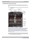
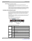
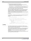
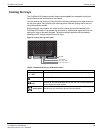
FortiGate-5140 shelf alarm panel
The FortiGate-5140 shelf alarm panel (SAP), located at the top of the FortiGate-5140 front
panel, provides LED indicators of FortiGate-5140 alarms, a telco alarm connector, an
alarm LED reset button, and console access to the FortiGate-5140 shelf managers. The
LED alarm indicators include critical, major, and minor alarms as well as three user
defined alarms.
The alarm LED reset button (RESET) on the shelf alarm panel activates the Alarm Cutoff
(ACO) state. When ACO is activated, the active alarm LEDs blink and all of the alarm
relays are deactivated.
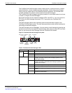
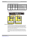
Figure 4: FortiGate-5140 shelf alarm panel front panel
Table 3: FortiGate-5140 shelf alarm panel LEDs
LED State Description
CRITICAL Off Normal operation.
Red Indicates a critical alarm.
Blinking
Red
Alarm cutoff (ACO) activated by pressing the alarm LED reset button.
MAJOR Off Normal operation.
Red Indicates a major alarm.
Blinking
Red
Alarm cutoff (ACO) activated by pressing the alarm LED reset button.
MINOR Off Normal operation.
Amber Indicates a minor alarm.
Blinking
Amber
Alarm cutoff (ACO) activated by pressing the alarm LED reset button.
USER1
USER2
USER3
Off Normal operation
Amber Indicates a user-definable alarm.
Blinking
Amber
Alarm cutoff (ACO) activated by pressing the alarm LED reset button.
CRITICAL
RESET
MAJOR
MINOR
USER1
USER2
USER3
5140SAP
SERIAL 1 SERIAL 2 ALARM
Retention
Screw
Retention
Screw
Telco Alarm
Interface
Alarm
LED Reset
Button
Minor Alarm (Amber)
Major Alarm (Red)
Critical Alarm (Red)
User 1 Alarm (Amber)
User 2 Alarm (Amber)
User 3 Alarm (Amber)
SERIAL 1 (Primary
Shelf Manager)
SERIAL 2 (Secondary
Shelf Manager)