


Power connection and configuration
FortiGate-5140-R Chassis Guide
01-30000-87705-20090108 27
http://docs.fortinet.com/ • Feedback
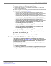
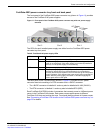
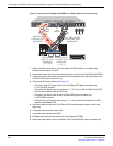
10 Connect the FortiGate-5053 power converter tray to AC power.
Only connect the power supplies that are installed in the FortiGate-5053 to AC power.
For example, if your FortiGate-5053 includes two FortiGate-5140 power supplies, the
power supplies will be installed in slots 1 and 2. In this case you should only connect
AC in connectors 1 and 2 to AC power. If your FortiGate-5053 power convertor tray
contains three power supples, connect all three AC in connectors to AC power.
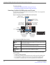
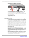
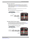
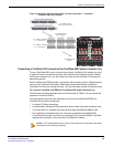
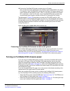
The photograph in Figure 18 shows how to connect four RTN (RED) and four -48V
(BLACK) wires to the FortiGate-5053 power convertor tray. This photograph also shows
the clear back cover of the FortiGate-5053 installed. You should install this cover using the
mounting hardware provided. Install the cover after connecting the power but before
turning the power on.
Figure 18: Wiring the FortiGate-5053 power converter tray
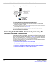
Connecting the FortiGate-5140 chassis to data center ground
The FortiGate-5053 power converter tray does not have a ground connector. So, even if
you are using a FortiGate-5053 power converter tray to supply DC power to your
FortiGate-5140, you must use the procedure “Connecting the FortiGate-5140 chassis to
data center ground” on page 19 to connect the FortiGate-5140 to data center ground.
Turning on FortiGate-5140 chassis power
If you are using a FortiGate-5053 power convertor, connect the FortiGate-5053 power
convertor to AC power. When the FortiGate-5140 power supplies start up the power
supply fans should begin operating. Each FortiGate-5140 power supply has two front
panel power LEDs (see Figure 11 on page 21). When the FortiGate-5053 power convertor
is operating normally, both of the FortiGate-5140 power supply LEDs should be lit for each
connected power supply.
If you are using data center DC power, turn on the power to the chassis according to the
requirements of your data center DC power system.
When the connected DC power source is turned on the FortiGate-5140 chassis powers
up. If the FortiGate-5140 is operating correctly, the following LEDs are lit:
• Green OK LED on each connected PEM (see Figure 9 on page 18). The PEMs are on
the FortiGate-5140 back panel (see Figure 2 on page 7).
• Green OK LED on all cooling fan trays (see Figure 8 on page 15). The cooling fan trays
are on the FortiGate-5140 front panel (see Figure 1 on page 6).