


Power connection and configuration
FortiGate-5140-R Chassis Guide
01-30000-87705-20090108 25
http://docs.fortinet.com/ • Feedback
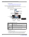
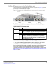
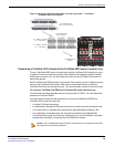
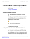
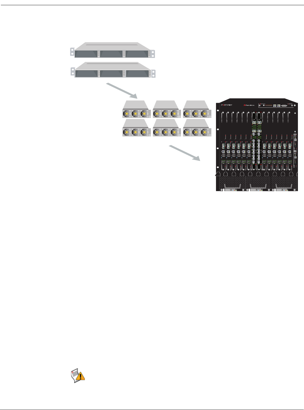
Figure 16: Redundant FortiGate-5053 power converter trays and 2 + 1 redundant
FortiGate-5140 power supplies
Connecting a FortiGate-5140 chassis to the FortiGate-5053 power converter tray
To use a FortiGate-5053 power converter tray with the FortiGate-5140 chassis you need
to make DC power connections between the FortiGate-5140 chassis and the FortiGate-
5053 power converter tray. You also need to the connect the FortiGate-5140 chassis to
data center ground.
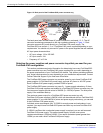
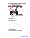
Each FortiGate-5140 PEM includes 4 connectors that connect power to 4 different power
zones in the FortiGate-5140 chassis. Each power zone supplies power to different
FortiGate-5140 slots and cooling fan trays. You should always connect all 4 power zones.
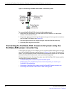
To connect a FortiGate-5140 PEM to a FortiGate-5053 power converter tray
The following procedure describes how to connect power to PEM A. You can repeat this
procedure to connect PEM B.
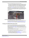
You need the following tools and equipment to connect a FortiGate-5140 PEM to a
FortiGate-5053 power converter tray:
• A number 2 Phillips screwdriver.
• An electrostatic discharge (ESD) preventive wrist or ankle strap with connection cord.
• Four black AWG-14 stranded wires with terminal lugs attached and labelled -48V
• Four red AWG-14 stranded wires with terminal lugs attached and labelled RTN
• A FortiGate-5053 power converter tray containing two or three FortiGate-5140 power
supplies and mounted in a rack near the FortiGate-5140 chassis.
Slot 1Slot 2Slot 3
2 FortiGate-5053
power convertor trays
1 FortiGate-5140
chassis
2 x 1200W = 2400W
2 + 1 redundancy
2 x 1200W = 2400W
2 + 1 redundancy
6 FortiGate-5140
power supplies
Slot 1Slot 2Slot 3
FAN TRAY FAN TRAYFAN TRAY
1311975312468101214
5140
C
R
IT
I
C
A
L
R
E
S
E
T
M
A
J
O
R
M
I
N
O
R
U
S
E
R
1
U
S
E
R
2
U
SE
R
3
5140SAP
SERIAL 1 SERIAL 2 ALARM
FILTER
12
0
12
10/100
link/Act
ETH0
Service
RESET
STATUS
Hot Swap
link/Act
ETH0
ETH1
10/100
5000SM
10/100
link/Act
ETH0
Service
RESET
STATUS
Hot Swap
link/Act
ETH0
ETH1
10/100
5000SM
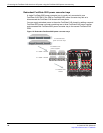
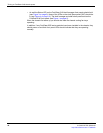
Caution: The FortiGate-5053 power convertor tray should not be connected to AC power
until specified in the following procedure.