


Power connection and configuration
FortiGate-5140-R Chassis Guide
01-30000-87705-20090108 21
http://docs.fortinet.com/ • Feedback
FortiGate-5053 power converter tray front and back panel
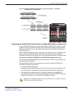
The front panel of the FortiGate-5053 power converter tray (shown in Figure 11) provides
access to the FortiGate-5140 power supplies.
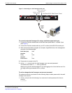
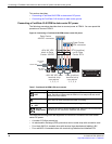
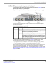
Figure 11: Front panel of the FortiGate-5053 power converter tray with one power supply
removed
The LEDs for each installed power supply are visible from the FortiGate-5053 power
converter tray front panel.
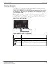
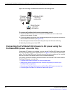
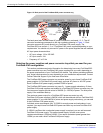
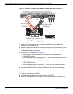
The back panel of the FortiGate-5053 (shown in Figure 12) includes one DC power
connector terminal consisting of a RTN connector and a -48VDC connector:
• The -48VDC connector is labelled V- and may also be labelled with -48V (BLACK).
• The RTN connector is labelled V+ and may also be labelled RTN (RED)
Each FortiGate-5140 PEM includes 4 connectors that connect power to 4 different power
zones in the FortiGate-5140 chassis. Each power zone supplies power to different
FortiGate-5140 slots and cooling fan trays. You should always connect all 4 power zones.
See “Connecting a FortiGate-5140 chassis to the FortiGate-5053 power converter tray” on
page 25 for details.
Table 8: FortiGate-5140 power supply LEDs
LED State Description
AC Power Green The power supply is connected to AC power.
Off The power supply is not receiving DC power. This can happen if an AC
cable is not connected, if the power supply is not correctly installed in
the slot, or if the power supply is not functioning.
DC Power Green The power supply is providing DC power.
Off The power supply is not providing DC power. If the AC power LED is lit
and the DC power LED is not, the power supply is not functioning
correctly and should be replaced. This LED can also go off if the power
supply overheats. If this happens the power supply stops supplying DC
power. After the power supply cools down in will start supplying DC
power again and this LED lights.
Slot 1
Slot 2
AC Power
LED
DC Power
LED
Slot 3