


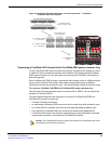
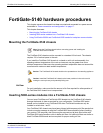

Connecting the FortiGate-5140 chassis to AC power using the FortiGate-5053 power converter tray
FortiGate-5140-R Chassis Guide
26 01-30000-87705-20090108
http://docs.fortinet.com/ • Feedback
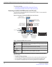
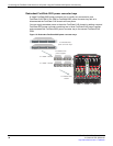
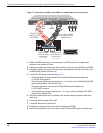
Figure 17: Connecting a FortiGate-5140 PEM to a FortiGate-5053 power converter tray
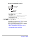
1 Attach the ESD wrist strap to your wrist and to an ESD socket or to a bare metal
surface on the chassis or frame.
2 Loosen the screws and remove the terminal block cover from the FortiGate-5140 PEM.
3 If required, loosen the screws and remove the clear plastic cover from the back of the
FortiGate-5053 power convertor tray.
4 Connect the DC power wires (see Figure 17):
• Connect 4 black DC power wires to the FortiGate-5053 power converter tray
V- 48V (BLACK) terminal
• Connect these black wires to connectors 1, 2, 3, and 4 on the FortiGate-5140 PEM
terminal strip labeled -48V/-60 VDC nom.
• Connect 4 red return wires to the FortiGate-5053 power converter tray
V+ RTN (RED) terminal.
• Connect these red wires to connectors 1, 2, 3, and 4 on the FortiGate-5140 PEM
terminal strip labeled RTN.
5 Secure the power wires to the FortiGate-5140 chassis using tie wraps and the back
cable tray.
6 If required, label the black wires -48V.
7 If required, label the red wires RTN.
8 Re-attach the terminal block cover to the FortiGate-5140 PEM.
9 Attach the clear plastic cover to the back of the FortiGate-5053 power converter tray.
12341234
-48V/-60 VDC nom RETURN
12341234
PEM
V-V+
100-240VAC 1 2 3RTN(RED) -48V(BLACK)
RTN (positive)
terminal strip
connectors
1, 2, 3, 4
Red RTN to
FortiGate-5053
RTN (RED)
-48V/-60 VDC
terminal strip
connectors
1, 2, 3, 4
Black -48V/-60 VDC
to FortiGate-5053
-48V(BLACK)
AC in
-48V
-48V
RTN
TERMINAL BLOCK COVER
Remove terminal block cover and
decable before removing PEM.
RTN
V+
(RTN)
(RED)
V-
-48V
(BLACK)