


FortiGate-5140 chassis front panel FortiGate-5140 chassis
FortiGate-5140-R Chassis Guide
6 01-30000-87705-20090108
http://docs.fortinet.com/ • Feedback
FortiGate-5140 chassis front panel
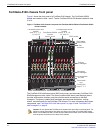
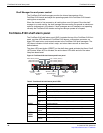
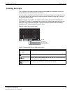
Figure 1 shows the front panel of a FortiGate-5140 chassis. Two FortiSwitch-5003A
boards are installed in slots 1 and 2. Twelve FortiGate-5001A-DW boards installed in slots
3 to 14.
Figure 1: FortiGate-5140 chassis front panel with FortiGate-5001A-DW and FortiSwitch-5003A
boards installed
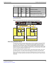
The FortiGate-5140 shelf alarm panel (SAP) and primary and secondary FortiGate-5140
Shelf Managers are also visible. The factory installed shelf alarm panel displays alarms,
provides a telco alarm interface, and also provides serial connections to the shelf
managers. The factory installed shelf managers provide power distribution, cooling,
alarms, and shelf status for the FortiGate-5140 chassis. For more information about these
components, see “FortiGate-5140 shelf alarm panel” on page 10 and “FortiGate-5140
shelf managers” on page 8.
FAN TRAY FAN TRAYFAN TRAY
1311975312468101214
5140
CRITICAL
RESET
MAJOR
MINOR
USER1
USER2
USER3
5140SAP
SERIAL 1 SERIAL 2 ALARM
FILTER
12
0
12
10/100
link/Act
ETH0
Service
RESET
STATUS
Hot Swap
link/Act
ETH0
ETH1
10/100
5000SM
10/100
link/Act
ETH0
Service
RESET
STATUS
Hot Swap
link/Act
ETH0
ETH1
10/100
5000SM
FortiGate-5001A-DW
boards
slots 4, 6, 8, 10,
12, and 14
Primary
shelf manager
Secondary
shelf manager
Cooling fan
trays 0, 1, 2
FortiGate-5001A-DW
boards
slots 3, 5, 7, 9,
11, and 13
FortiSwitch-5003A
boards
slots 1 and 2
Front cable
tray
ESD socket
Slot
numbers
Shelf alarm
panel (SAP)
Front accessible
air filter
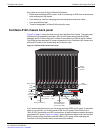
Caution: Do not operate the FortiGate-5140 chassis with open slots on the front panel. For
optimum cooling performance and safety, the slots must contain a FortiGate-5000 series
board or an air baffle slot filler. As well the removable terminal block cover must be installed
over the power connectors on the back of the chassis.