


FortiGate-5140 chassis Cooling fan trays
FortiGate-5140-R Chassis Guide
01-30000-87705-20090108 15
http://docs.fortinet.com/ • Feedback
Cooling fan trays
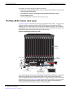
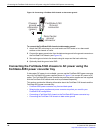
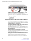
The FortiGate-5140 chassis contains three interchangeable hot-swappable cooling fan
trays installed at the front bottom of the chassis.
You can remove any fan tray by lifting the front cable tray, pressing the hot swap button on
the tray front panel, fully loosening the mounting knots, and then pulling the fan tray out
using the extraction handle.
Each cooling fan tray contains two radial fans for cooling the modules installed in the
FortiGate-5140 chassis. Fan speeds are monitored by a tachometer signal sent from the
cooling fan trays to the shelf manager. The shelf manager regulates the fan speed by
adjusting the DC voltage supplied to the fan trays.
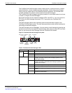
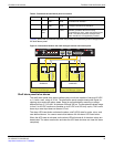
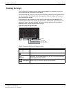
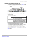
Figure 8: Cooling fan tray front panel
Table 6: FortiGate-5140 fan tray LEDs and controls
LED/Control Description
OK (operate)
LED
Green when the fan tray is powered and operating normally.
Alarm LED Normally off. Turns red when there is a problem with the fan tray.
HS (hot swap)
LED
Normally off. Blinking blue indicates that the fan tray is entering the hot
swap mode. Solid Blue indicates that the fan tray is in hot swap mode and
can be removed from the chassis.
HS (hot
swap) button
Press the HS button to enter hot swap mode. When the HS LED becomes
solid blue you can remove the fan tray from the chassis.
FAN TRAY
Hot swap button
Hot swap LED
Alarm LED
OK LED