


Installing a FastIron LS Switch
September 2007 © 2007 Foundry Networks, Inc. 3 - 5
Preparing the Installation Site
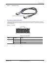
Cabling Infrastructure
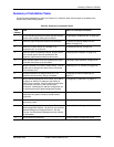
Ensure that the proper cabling is installed at the site. See “Hardware Specifications” on page 2-1 or
www.foundrynetworks.com for a summary of supported cabling types and their specifications.
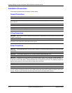
Installation Location
Before installing the device, plan its location and orientation relative to other devices and equipment. Switches can
be mounted in a standard 19-inch equipment rack, on a flat surface, or on a wall. Be sure to follow the guidelines
below when choosing a location.
The site should:
• Maintain temperatures within 0 to 50 °C (32 to 122 °F) and humidity levels within 5% to 95%, non-condensing.
• Allow a minimum of 3" of space between the sides and the back of the device and walls or other obstructions
for proper air flow.
• Allow at least 3" of space at the front of the device for the twisted-pair, fiber-optic, and power cabling.
• Be accessible for installing, cabling and maintaining the devices.
• Allow the status LEDs to be clearly visible.
• Allow for twisted-pair cable to be always routed away from power lines, fluorescent lighting fixtures and other
sources of electrical interference, such as radios and transmitters.
• Allow for the unit to be connected to a separate grounded power outlet that provides 100 to 240 VAC, 50 to 60
Hz, is within 2 m (6.6 feet) of each device and is powered from an independent circuit breaker. As with any
equipment, a filter or surge suppressor is recommended.
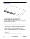
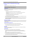
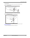
Installing the Device
You can install Foundry systems on a desktop, in an equipment rack, or on the wall.
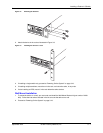
WARNING: Make sure the rack or cabinet housing the device is adequately secured to prevent it from becoming
unstable or falling over.
WARNING: Mount the devices you install in a rack or cabinet as low as possible. Place the heaviest device at the
bottom and progressively place lighter devices above.