


Foundry FastIron LS Layer 2 Compact Switch Hardware Installation Guide
4 - 6 © 2007 Foundry Networks, Inc. September 2007
2. Remove the new module from its protective packaging.
3. Gently insert the fiber optic module into the port until the module clicks into place. The module is keyed to
prevent incorrect insertion.
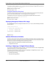
Cabling a Fiber Optic Module
To cable a fiber optic module, do the following:
1. Remove the protective covering from the fiber-optic port connectors and store the covering for future use.
2. Before cabling a fiber optic module, Foundry strongly recommends cleaning the cable connectors and the
port connectors. For more information, see “Cleaning the Fiber-Optic Connectors” on page 4-6.
3. Gently insert the cable connector(s) (a tab on each connector should face upward) into the port connector(s)
until the tabs lock into place.
4. Observe the link and active LEDs to determine if the network connections are functioning properly. For more
information about the LED indicators, see Table 4.2 on page 4-7.
Cleaning the Fiber-Optic Connectors
To avoid problems with the connection between the fiber optic module (SFP (mini-GBIC) or XFP) and the fiber
cable connectors, Foundry strongly recommends cleaning both connectors each time you disconnect and
reconnect them. In particular, dust can accumulate in the connectors and cause problems such as reducing the
optic launch power.
To clean the fiber cable connectors, Foundry recommends using the fiber-optic reel-type cleaner that shipped with
your FastIron LS. You can also purchase this type of cleaner from the following Website:
http://www.fisfiber.com/Home_Page.asp
When not using an SFP or XFP connector, make sure to keep the protective covering on.
Testing Connectivity
You can observe the LEDs related to network connection.
Observing LEDs
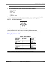
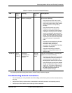
After you install the network cables, you can observe certain LEDs to determine if the network connections are
functioning properly. Table 4.2 outlines the LEDs related to the network connections, the desired state of each
LED, possible abnormal states of each LED, and what to do if an LED indicates an abnormal state.