


Installing a FastIron LS Switch
September 2007 © 2007 Foundry Networks, Inc. 3 - 17
NOTE: You need to run a terminal emulation program on the PC.
2. Open the terminal emulation program and set the session parameters as follows:
• Baud: 9600 bps
• Data bits: 8
• Parity: None
• Stop bits: 1
• Flow control: None
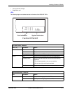
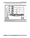
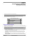
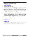
The EIA/TIA 232 serial communication port serves as a connection point for management by a PC or SNMP
workstation. Foundry switches come with a standard male DB-9 connector, shown in Figure 3.11.
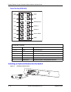
Figure 3.11 Serial Port (DB-9 DTE) Pin-Out
Most PC serial ports also require a cable with a female DB-9 connector.
Terminal connections will vary, requiring either a DB-9 or DB-25 connector, male or female.
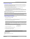
Serial cable options between a Foundry switch or router and a PC or terminal are shown in Table 3.3.
Wiring Map for Serial Cable
NOTE: As indicated in Table 3.3, some of the wires should not be connected.
Table 3.3: Serial Cable Wiring
Switch’s 9-Pin
Serial Port
Null Modem PC’s 9-Pin
DTE Port
2 RXD (receive
data)
<---------------------------- 2 TXD
(transmit data)
3 TXD (transmit
data)
----------------------------> 3 RXD
(receive data)
5 SGND (signal
ground)
----------------------------- 5 SGND
(signal ground)
No other pins are used.
1
5
6
9