


Maintaining the FastIron LS Hardware
September 2007 © 2007 Foundry Networks, Inc. 5 - 7
1. Put on the ESD wrist strap and ground yourself by attaching the clip end to a metal surface (such as an
equipment rack) to act as ground.
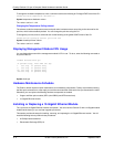
2. Remove the new module from its protective packaging.
3. Gently insert the fiber optic module into the port until the module clicks into place. The module is keyed to
prevent incorrect insertion.
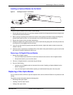
Cabling a Fiber Optic Module
To cable a fiber optic module, do the following:
1. Remove the protective covering from the fiber-optic port connectors and store the covering for future use.
2. Before cabling a fiber optic module, Foundry strongly recommends cleaning the cable connectors and the
port connectors. See “Cleaning the Fiber-Optic Connectors” on page 5-7.
3. Gently insert the cable connector(s) (a tab on each connector should face upward) into the port connector(s)
until the tabs lock into place.
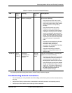
4. Observe the link and active LEDs to determine if the network connections are functioning properly. For more
information about the LED indicators, see Table 4.2 on page 4-7.
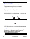
Cleaning the Fiber-Optic Connectors
To avoid problems with the connection between the fiber optic module (SFP (mini-GBIC) or XFP) and the fiber
cable connectors, Foundry strongly recommends cleaning both connectors each time you disconnect and
reconnect them. In particular, dust can accumulate in the connectors and cause problems such as reducing the
optic launch power.
To clean the fiber cable connectors, Foundry recommends using the fiber-optic reel-type cleaner that shipped with
your FastIron LS. You can also purchase this type of cleaner from the following Website:
http://www.fisfiber.com/Home_Page.asp
When not using an SFP or XFP connector, make sure to keep the protective covering on.
Digital Optical Monitoring
You can configure your Foundry device to monitor XFPs in the system either globally or by specified port. If
monitoring is enabled, console messages, syslog messages, and SNMP traps are sent when XFP operating
conditions warrant and a port is enabled.
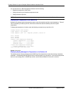
To configure all XFP ports for optical monitoring, use the following command:
FLS648 Switch(config)#optical-monitor
To configure a specific XFP port for optical monitoring, use the following command:
FLS648 Switch(config)#interface ethernet 1/1
FLS648 Switch(config-if-e10000-1/1)#optical-monitor
To configure a range of XFP ports for optical monitoring, use the following command:
FLS648 Switch(config)#interface ethernet 1/1 to 1/2
FLS648 Switch(config-mif-e10000-1/1-1/2)#optical-monitor
Syntax: [no] optical-monitor <alarm-interval>
The optional <alarm-interval> variable sets the interval in minutes between which alarms or messages are sent.
The default interval is 3 minutes.
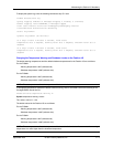
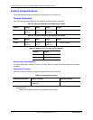
You can view the XFP optical monitoring information using the show optic command as shown: