


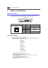
2-10 4. Modular Jack (MJ1/MJ2)
4. Modular Jack (MJ1/MJ2)
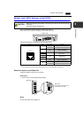
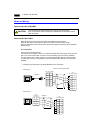
Modular Jack 1 (MJ1)
This is a modular connector used for connection for screen data transfer, temperature controller,
barcode reader, card recorder (UG00P-MR) or serial extension I/O (UG00P-U2).
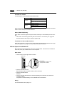
The pins of modular jack 1 correspond to signals as given below.
* The maximum current for external supply (+5V) is 150 mA when the MJ1 or MJ2 is used.
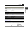
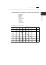
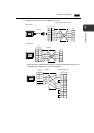
Editor (UG00S-CW) Setting
1. The use of modular jack 1 can be set on the editor.
2. Select [Modular] from the [System Setting] menu. The [Modular Jack] dialog is displayed. Select
the use of modular jack 1 from the following options.
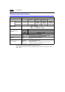
*1 Refer to “Transferring Screen Data” (page 2-17).
*2 Select this option when connecting the card recorder (UG00P-MR).
*3 Refer to “Barcode Reader Connection” (page 2-17).
*4 Select this open when “Multi-link 2” is selected for [Connection] and “1” is set for [Local Port] on the
[Comm. Parameter] dialog.
*5 Select this option when using the ladder transfer function.
*6 Select this option for Modbus slave connection.
*7 Select this option when connecting the printer with serial interface.
Refer to page 2-18.
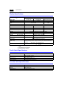
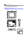
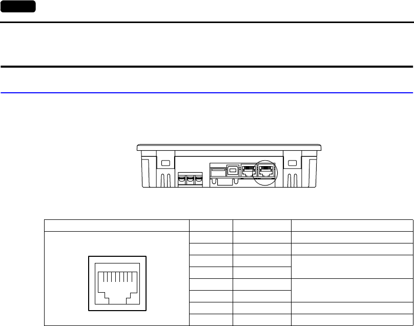
Bottom View
MJ1 Pin No. Signal Name Contents
1 +SD/RD RS-485 +data
2 −SD/RD RS-485 − data
3+5V
Externally supplied +5 V
Max. 150 mA
*
4+5V
5SG
Signal ground
6SG
7 RD RS-232C receive data
8 SD RS-232C send data
12345678
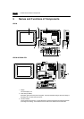
Modular Jack 1
[Editor Port]
*1
[Card Recorder]
*2
[Barcode]
*3
[UG00P-U2]
[Multi-Link]
*4
[Temp. /PLC2Way]
[UG-Link]
[Ladder Tool]
*5
[Modbus Slave]
*6
[Printer (Serial Port)]
*7