4-4 2. DIP Switch Setting
2. DIP Switch Setting
DIP Switch (DIPSW) Setting
When setting the DIP switch, turn the power off.
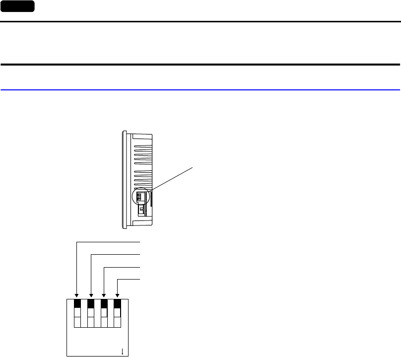
Terminating Resistance Setting (DIPSW1, 2, 3)
Set the terminating resistance for RS-422/485 connection.
• MJ1 can be used for RS-232C or RS-485 (2-wire) connection.
For the following connections, set DIPSW 1 to the ON position.
- Master station for multi-link 2 connection
- Temperature controller network/PLC2Way connection via RS-485
- Card Recorder: Connection with the UG00P-MR (optional)
- Serial extension I/O: Connection with the UG00P-U2 (optional)
- Connection to the UG230 at the termination of UG-link connection via RS-485
• MJ2 can be used for RS-232C or RS-422 (4-wire) connection.
- For connection to the PLC through the RS-422 interface (4-wire connection) at MJ2, set
DIPSW2 and 3 to the ON position.
- For connection to the PLC through the RS-422 interface (2-wire connection) at MJ2, set
DIPSW3 to the ON position.
CF Auto Load (DIPSW4)
A screen data file saved on a CF card can be auto-loaded as described below.
1. Transfer screen data from the computer to a CF card. (Refer to the User's Manual <Function>
(FEH376) for more information.)
2. Set DIPSW4 in the ON position, and insert the CF card that contains the screen data file.
3. Turn the unit on. The screen data is automatically loaded into the FLASH memory of the unit.
Side View
DIP switch
1234
ON
CF auto load (for USB/UG230A-DCL)
MJ2 (modular jack 2) SD terminating resistance for RS-422
MJ1 (modular jack 1) terminating resistance for RS-485
MJ2 (modular jack 2) RD terminating resistance for RS-422


