2-14 4. Modular Jack (MJ1/MJ2)
Notes on Wiring
Notes on the Use of MJ1/MJ2
Notes on the Use of MJ2
Either the RS-232C or RS-422 port can be selected for MJ2 with the slide switch.
When the slide switch is set to RS-232C, MJ2 is connected in the same manner as MJ1.
When the slide switch is set to RS-422, extra care should be taken if connecting a device adapted to
RS-485 (2-wire).
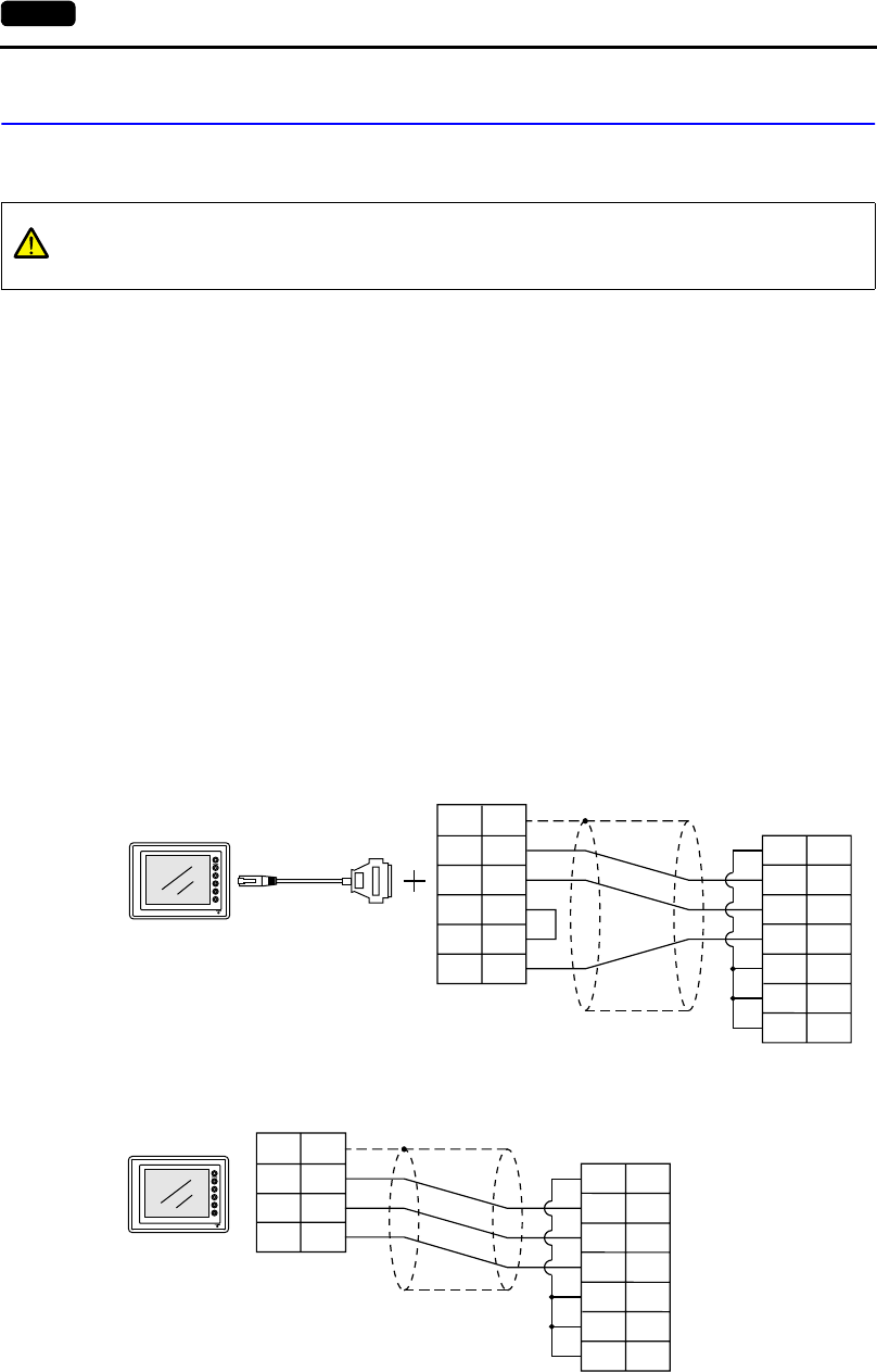
PLC connection
There are two connecting methods.
One method uses an adaptor UG30C-J for connection between MJ2 and the D-sub 25-pin connector
plus a PLC communication cable (as shown in the User’s Manual <PLC Connection> (FEH380)).
The other method uses a UG00C-P cable for connection between MJ2 and a PLC interface cable.
For information on the PLC wiring diagram, refer to the separate User’s Manual <PLC Connection>
(FEH380).
• Connecting to an RS-232C port (example: Mitsubishi A1SJ71UC24-R2):
CAUTION
The metal shell of the UG230 modular jack is used as SG (signal ground).
Fuji’s communication cable for modular jack, shielded cable, is connected to the SG
inside the UG230.
With UG30C-J
With UG00C-P
PLC
1
2
3
4
5
7
RD
SD
RS
CS
DR
SG
CD
1
2
3
5
6
7
8
FG
SD
RD
RS
CS
SG
MJ2
UG30C-J
D-sub 25-pin (Male)
D-sub 9-pin (Male)
POD PLC communication cable
PLC
RD
SD
RS
CS
DR
SG
CD
1
2
3
5
6
7
8
SG
SD
RD
SG
MJ2
SHELL
8
7
5
RJ-45 8-pin
UG00C-P
D-sub 9-pin (Male)


