


9
2.2 Appearance and Part Names
■ Appearance and Part Names
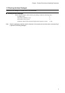
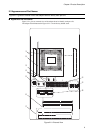
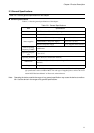
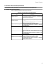
Figure 2.2-1 gives an external view of the adapter board to identify each part of it.
The adapter board illustrated in Figure 2.2-1 is in the factory default states.
Figure 2.2-1 External View
Figure 2.2-1 gives an external view of the adapter board to identify each part of it.
➆
➅
➄
➀
➉
➈
➇
➃
➂
➁
INIT
TRST
EML
EML
USR
USR
C2(SC4,5)
−+
C6(SC6,7)
+
−
1234
12345678
ON
SW2
SW1ASEL
1
2
3
RD
A1
A2
A3
A4
A5
A6
A7
A16
A17
A18
A19
A20
A21
A8
A9
A10
A11
A12
A13
A14
A15
SW3
SW4
+
−
C11(SC10,11)
+
−
C7(SC8,9)
12345678
ON ON
12345678
ON
X0
USR
X1
EML
X0/X1
X0A
USR
X1A
EML
X0A/X1A
S4
SC2
S5
SC3
CN5
VSEL1
USR
EML
VSEL2
USR
C
VSEL3
B
A
VSEL4
USR
EML
S6
S7
S8
S9
M2(SC1)
Chapter 2 Product Description