


28
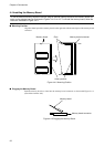
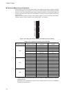
5.2 Setting the Clock Supply Circuit
■ Installing the Oscillator
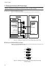
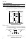
To supply a clock signal from the adapter board to the main clock (X0/X1) and subclock (X0A/X1A)
of the evaluation MCU, install an oscillator and a capacitor on the oscillator IC sockets (SC2 and
SC3) on the adapter board, respectively. Figure 5.2-1 shows how to install the oscillator and capaci-
tor.
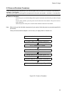
Figure 5.2-1 Installing the Oscillator and Capacitor
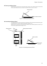
■ Installing the Oscillator
To supply a clock signal from the adapter board to the main clock (X0/X1) and subclock (X0A/X1A)
of the evaluation MCU, install an oscillator and a capacitor on the oscillator IC sockets (SC2 and
SC3) on the adapter board, respectively. Figure 5.2-1 shows how to install the oscillator and capaci-
tor.
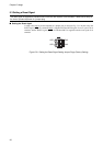
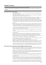
• For the frequency and other specifications of the oscillator, refer to the data sheet for the eval-
uation MCU.
• For the capacitance of the capacitor, refer to the data sheet for the oscillator.
• Prepare the oscillator and the capacitor as neither of them is bundled with this product.
Figure 5.2-1 Installing the Oscillator and Capacitor
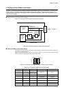
To supply a clock signal from the adapter board to the main clock (X0/X1) and subclock (X0A/X1A) of the eval-
uation MCU, install an oscillator and a capacitor on the oscillator IC sockets (SC2 and SC3) on the adapter
board, respectively. Figure 5.2-1 shows how to install the oscillator and capacitor.
X0/X1
8
7
6
5
1
2
3
4
X0
EML
USR
USR
EML
X1
X0A/X1A
X0A
EML
USR
USR
EML
X1A
X1
X0
GND GND
8
7
6
5
1
2
3
4
GND GND
X1
X0
X0
X1
X0A/PF5
X1A/PF6
Evaluation
MCU
Flat cable
connector
(MCU mounting
part)
Adapter Board
User system
(Board)
Oscillator
Capacitor Capacitor
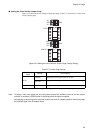
Please mount a capacitor in No. 2,
No. 4 terminal or No. 3, and No. 4
terminal.
Please mount a capacitor in No. 5,
No. 6 terminal or No. 5, and No. 7
terminal.
Chapter 5 Usage