


26
5.1 Setting up the Evaluation MCU Power Supply
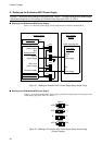
■ Setting up the Evaluation MCU Power Supply
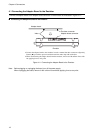
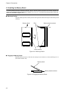
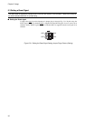
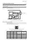
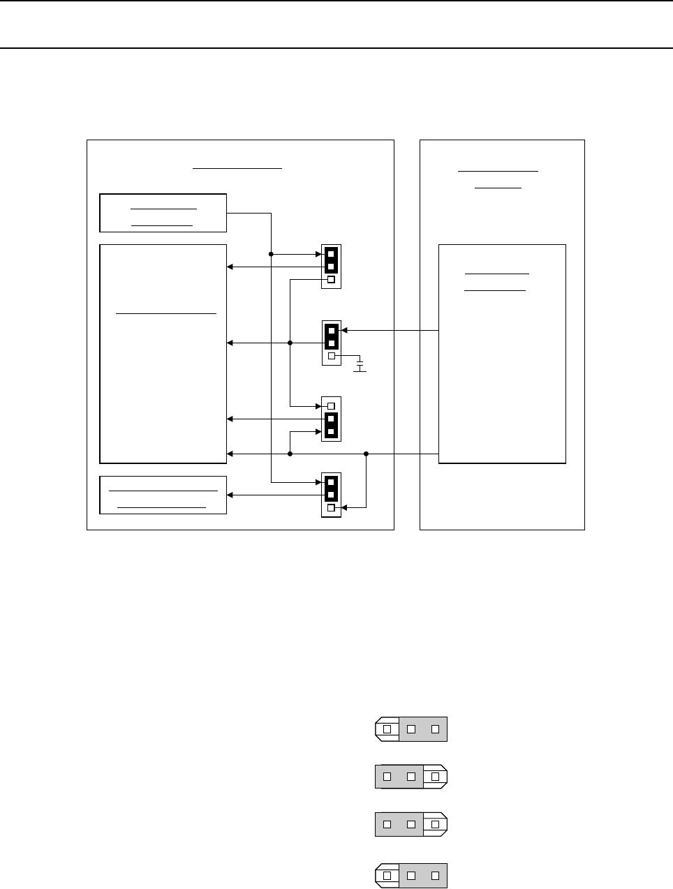
Figure 5.1-1 shows the power supply circuit configuration around the evaluation MCU.
Figure 5.1-1 Settings of Evaluation MCU Power Supply Setup Jumper Plugs
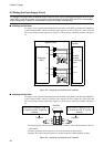
■ Setting up the Evaluation MCU Power Supply
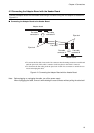
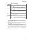
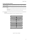
Table 5.1-1 lists the evaluation MCU power supply specifications depending on the settings of indi-
vidual jumper plugs from VSEL1 to VSEL4.
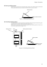
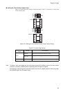
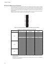
Figure 5.1-2 Settings of Evaluation MCU Power-Supply Setup Jumper Plugs
(Factory Settings)
Figure 5.1-1 shows the factory settings of the jumper plugs; Table 5.1-1 lists the evaluation MCU power supply
specifications depending on the settings of individual jumper plugs from VSEL1 to VSEL4.
VSEL1
VSEL2
VSEL3
VSEL4
USER
EML
GND
C
USER
A
B
0.1uF
EML
USER
+3.3V
Emulators
connector
Emulator
power supply
only
Evaluation MCU
Internal
power supply
Main clock
power supply
I/O power-supply
External memory
emulation part
Capacitor
Flat cable
connector
Internal
MCU
power supply
MCU
I/O
power-supply
Adapter Board
User System
(Board)
MCU mounting part
VSEL1
USR EML
VSEL2
USR C
VSEL3
B
VSEL4
USR EML
A
Chapter 5 Usage