


35
Chapter 6 Cautions
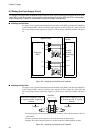
■ General Cautions on the Adapter
• Before setting a jumper plug or switch on the adapter board, turn off all of the adapter, emu-
lator, and user system.
• The settings of jumper plugs VSEL1 to VSEL4 are related to power supply. Setting these
jumper plugs incorrectly can destroy the entire system.
• When the user system supplies a clock signal to the evaluation MCU, the wiring pattern from
the clock signal source on the user system side may be too long to provide oscillation.
• When the user system supply a clock signal to the evaluation MCU using an oscillator, the
evaluation MCU has a restriction that, if the X0 or X1 pin must be opened, the jumper plug
for selecting the corresponding clock signal source must be removed. This also applies to X0A
and X1A.
• When the emulator is used, INITX pin control source of the evaluation MCU' to the emulator
position set the jumper plug to a reset signal setting.When the emulator is being used, the eval-
uation MCU’s INITX pin is controlled by the emulator and the reset signal from the user sys-
tem is input to the evaluation MCU via the emulator. The reset timing is therefore delayed
several clock cycles from the actual reset timing.
The reset command of the emulator only resets the evaluation MCU; it does not reset the user
system.
In addition, the signal sent from the user system to the INITX pin during a break is masked
by the emulator.
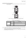
• The pin state of the user bus when the evaluation MCU is in the user hold/low power con-
sumption mode is the same as the one stated in the Evaluation MCU hardware manual.
• The flat cable (long) can be used when the MCU’s clock frequency is low or when the load
on user pins is very light. Usually, the flat cable (standard) should be used.
• When the adapter and header are used, the MCU on the user system must always be socket
mounted. The IC socket must be the designated IC socket.
• No power is supplied to the user system from the adapter, header, or emulator.
• When the external memory emulation function is not used, set all the memory connection
switches to OFF. If external signals are applied with the memory connection switches set to
ON, drive the adapter at a current of at least ±750µA. If the drive current is lower than
±750µA, a normal potential may not be obtained due to the bus hold feature of the buffer IC.
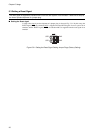
■ Cautions to be observed when the External Memory Emulation Function
• When external-memory emulation is used, set those memory connective switches to ON
which correspond to the effective address bus signal (equivalent to A[21:1], variable with
memory size setting) and control line (equivalent to RDX).
• A buffer IC is connected to the effective address bus signal (variable with the memory size set-
ting) and control line used for external-memory emulation. A capacitance of about 6 pF is
therefore added to each of the signal conductors.
• As a buffer IC is connected to the effective address bus signal and control line used for exter-
nal-memory emulation, each signal conductor connected to the memory board involves a de-
lay of about 6 ns.
• As the data bus used for external-memory emulation is connected directly to the data bus sig-
nal (equivalent to D[31:16]), the external I/O power supply to the evaluation MCU must al-
ways be +3.3 V. The external I/O power supply exceeding +3.3 V canbreak the memory board.
• As the data bus used for external-memory emulation is connected directly to the data bus of
the evaluation MCU, a capacitance of about 6 pF is added to each signal conductor when the
This chapter lists precautions and important notes on use of this product.
That extra cautions apply to the adapter when the external-emulation memory and power-on debug functions
are used.