


31
5.4 Setting a External Memory Emulation
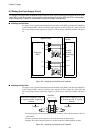
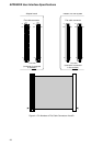
■ External Memory Emulation Block Diagram
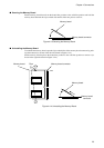
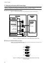
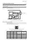
Figure 5.4-1 shows the external memory emulation block diagram.
Figure 5.4-1 External Memory Emulation Block Diagram
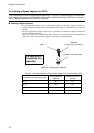
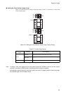
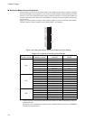
■ SettingtheMemorySizeSelectSwitch
The memory size select switch select the size of the memory board to be connected to use the exter-
nal memory emulation function.
Figure 5.4-2 shows the factory settings of the switch; Table 5.4-1 lists the memory board sizes and
effective addresses depending on the settings of the switch.
Figure 5.4-2 Setting the Memory Size Select Switch (Factory Setting)
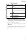
Table 5.4-1 The Memory Size Select Switch Settings
Figure 5.4-1 shows the external memory emulation block diagram, figure 5.4-2 and table 5.4-1 show the set-
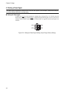
ting the memory size select switch and the factory settings of the memory size select switch, figure 5.4-3
shows the factory settings of the setting the memory connective switches; Table 5.4-2 lists the memory con-
nective switch settings.
ASEL3 ASEL2 ASEL1 Memory board size Affective addresses
111
2 MWords A[21:1]
110
1 0 1 1 MWords A[20:1]
1 0 0 512 KWords A[19:1]
0 1 1 256 KWords A[18:1]
0 1 0 128 KWords A[17:1]
0 0 1 64 KWords A[16:1]
0 0 0 32 KWords A[15:1]
P4[5:0],P3[7:0],P2[7:1],P5[4]
P1[7:0],P0[7:0]
A
*OE
Y
GND
Evaluation
MCU
74LVCH16244A
External-
memory
emulation
circuit
Adapter board
To header
Flat cable
connector
Memory
connective
switches
Data bus
Address bus
SW1
1
2
3
ON
1234
ASEL
Chapter 5 Usage