


15
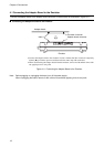
3.2 Connector and IC Socket Specifications
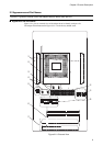
■ Connector and Socket Specifications
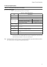
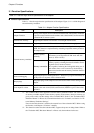
Table 3.2-1 lists the specifications of the connectors and sockets.
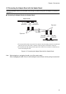
Table 3.2-1 Connector and IC Socket Specifications
The table below lists the specifications of the connectors and sockets on the adapter board.
Item Description
Emulator connector
Use this connector to connect the emulator to the adapter.
For connecting the emulator, see Section 4.1 "Connecting the
Adapter Board and the Emulator".
Flat cable connectors
Connect the adapter to the header using flat cables coming with
the adapter.
For connecting the flat cables, see Section 4.2 "Connecting the
Adapter Board and the Header Board".
Evaluation MCU mounting IC
socket
Mount the evaluation MCU (PGA-401P package).
For mounting the evaluation MCU, see Section 4.3 "Mounting
the Evaluation MCU".
Memory board connector
Mount an optional memory board.
For mounting the memory board, see Section 4.4 "Mounting
the Memory Board".
Oscillator IC sockets
Mount an oscillator and a capacitor authorized for the oscilla-
tor.
For mounting the oscillator and capacitor, see Section 5.2 "Set-
up for Clock Supply".
DVCCbypasscapacitormounting
sockets
If the evaluation MCU has an integrated digital power supply
(such as a DVCC power supply), a bypass capacitor can be
mounted on the digital power supply as required.
For mounting the bypass capacitor, see Section 4.5 "Mounting
the DVCC Bypass Capacitor".
Chapter 3 Functions